High-precision micro/nano-scale machining system

a micro/nano-scale, high-precision technology, applied in the direction of turning machine accessories, manufacturing tools, saw chains, etc., can solve the problems of high equipment and procedures, complex masking and etching steps of microfabrication and nanofabrication processes to form features such as channels and trenches, and achieve high precision

Inactive Publication Date: 2011-06-09
THE BOARD OF TRUSTEES OF THE UNIV OF ILLINOIS
View PDF11 Cites 16 Cited by
  • Summary
  • Abstract
  • Description
  • Claims
  • Application Information

AI Technical Summary

Benefits of technology

[0010]A high precision micro/nanoscale machining system is provided according to embodiments of the present invention. A multi-axis movement machine provides relative movement along multiple axes between a workpiece and a tool holder. A cutting tool is disposed on a flexible cantilever held by the tool holder, th...

Problems solved by technology

Microfabrication and nanofabrication processes to form features such as channels and trenches often involve complex masking and etching steps.
These processes, while successful, require highly expensive equipment and procedures to conduct micro- or nanofabrication steps.
However, the working volumes of these AFMs tend to be very limited.
Further, the length of the scribes is typically limited to between a few microns and tens of microns, and the speed of the piezoelectric stages of these machines (between 0.006 and 1.2 mm/min, wi...

Method used


Image

  • High-precision micro/nano-scale machining system
  • High-precision micro/nano-scale machining system
  • High-precision micro/nano-scale machining system

Examples


Embodiment Construction

[0032]In typical mechanical scribing processes, a key goal is to achieve high rigidity, which is deemed critical to accurate positioning and cutting. Therefore, conventional tools are designed to be rigid, and any deflection is deemed undesirable. In some conventional tools, rigid micro groove cutting tools and thread cutting tools have been created using focused ion beam (FIB) machining. Such tools have been used to cut features using a turning process and system. The rigid tools are used along with an extremely stiff and high-precision machine.

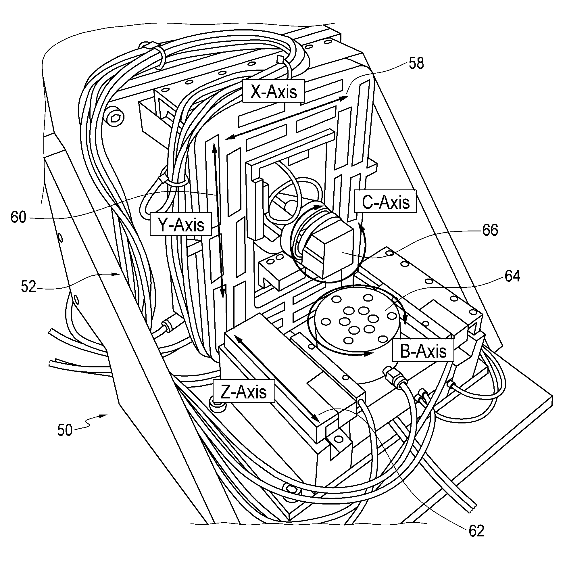
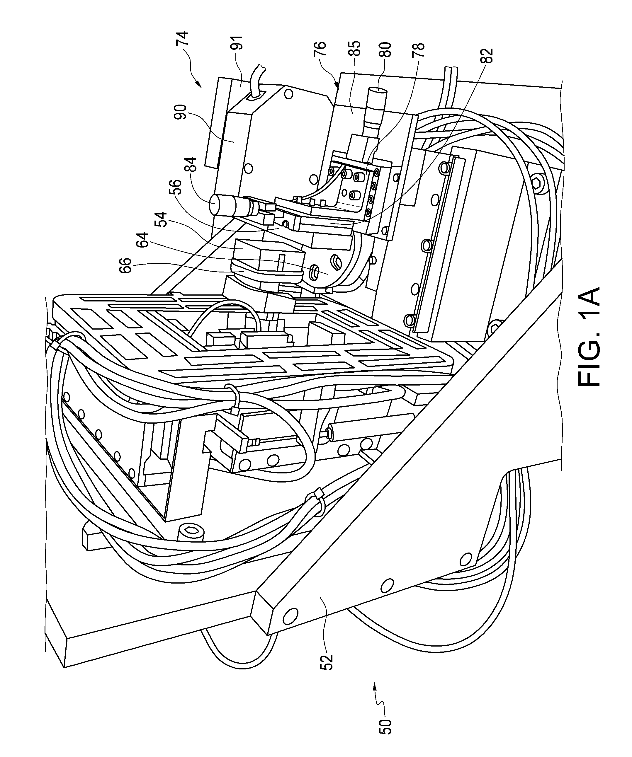
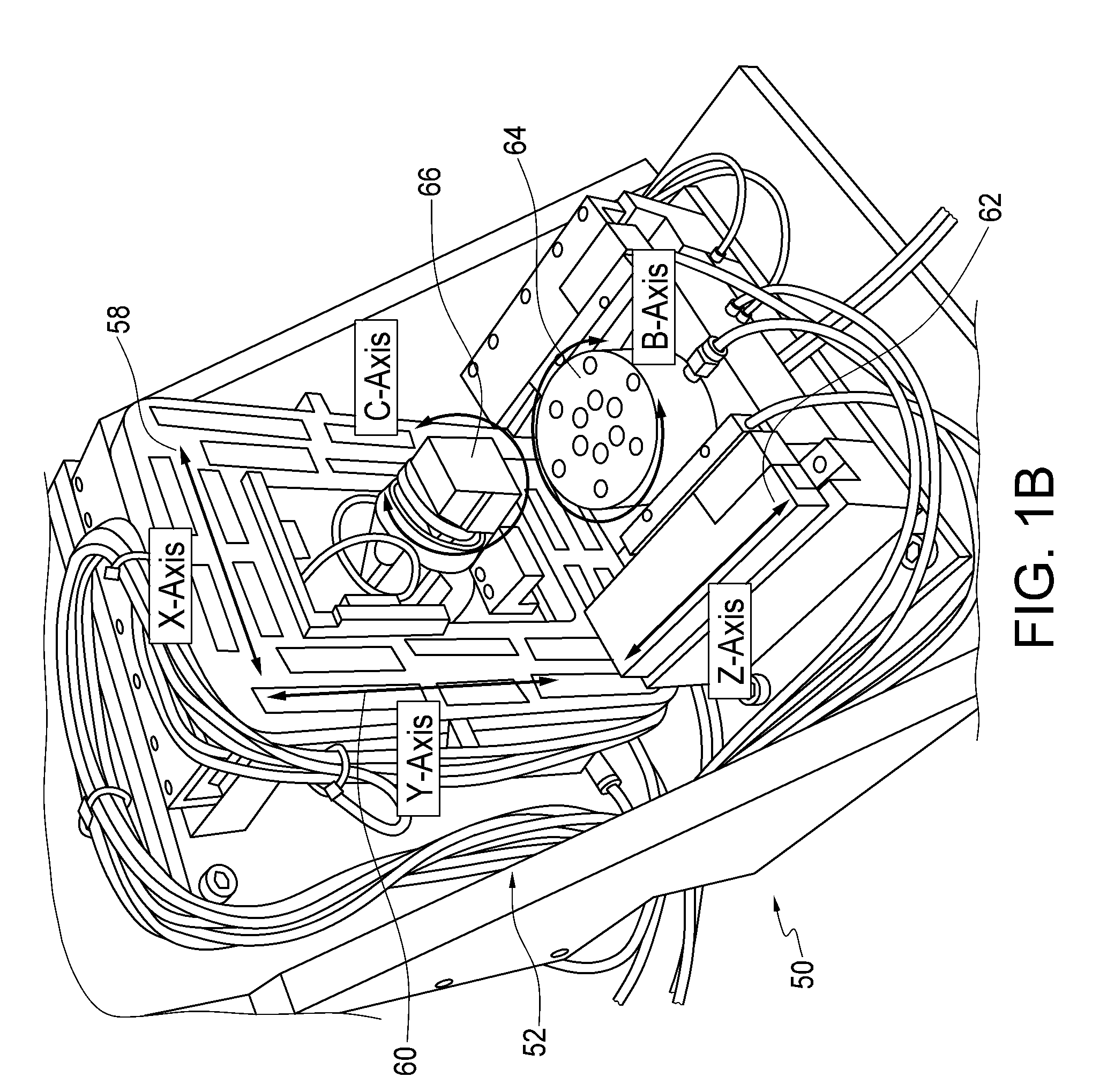
[0033]Embodiments of the present invention use a different approach, employing a flexible cutting tool that eliminates the need for the machine to be extremely rigid and relaxes requirements on position sensing and position control. This provides a relatively inexpensive cutting process compared to conventional high precision processes, such as diamond scribing / diamond turning processes.

[0034]An embodiment of the invention is a high precisio...


PUM

PropertyMeasurementUnit
Timeaaaaaaaaaa
Timeaaaaaaaaaa
Forceaaaaaaaaaa

Abstract

A high precision micro/nanoscale machining system. A multi-axis movement machine provides relative movement along multiple axes between a workpiece and a tool holder. A cutting tool is disposed on a flexible cantilever held by the tool holder, the tool holder being movable to provide at least two of the axes to set the angle and distance of the cutting tool relative to the workpiece. A feedback control system uses measurement of deflection of the cantilever during cutting to maintain a desired cantilever deflection and hence a desired load on the cutting tool.

Description

PRIORITY CLAIM AND REFERENCE TO RELATED APPLICATION[0001]This application claims the benefit of U.S. Provisional Application Ser. No. 61 / 240,417, filed Sep. 8, 2009, under 35 U.S.C. §119, which is incorporated by reference herein.STATEMENT OF GOVERNMENT INTEREST[0002]This invention was made with Government support under Contract No. DMI-0328162 awarded by National Science Foundation and under Contract Numbers DE-FG02-07ER46453 and DE-FG02-04ER46471 awarded by the Department of Energy. The Government has certain rights in the invention.FIELD OF THE INVENTION[0003]A field of the invention is microfabrication and nanofabrication.BACKGROUND OF THE INVENTION[0004]Microfabrication and nanofabrication processes to form features such as channels and trenches often involve complex masking and etching steps. These processes, while successful, require highly expensive equipment and procedures to conduct micro- or nanofabrication steps.[0005]Some efforts have been made to find simpler ways to c...

Claims


Application Information

Patent Timeline
IPC IPC(8): B26D3/06B26D5/02
CPCB26D1/0006B26D3/06B26D3/08B26D2001/002Y10T82/2585B26D2001/006Y10T82/2502Y10T82/10Y10T82/2535B26D2001/0053Y10T83/0304Y10T83/929
Inventor KAPOOR, SHIV G.BOURNE, KEITH ALLENDEVOR, RICHARD E.
Owner THE BOARD OF TRUSTEES OF THE UNIV OF ILLINOIS
Why Eureka
Try Eureka