
Carbon nanotube assembly and electrically conductive film

a carbon nanotube and electrically conductive film technology, applied in the direction of electrically conductive paints, conductors, non-metal conductors, etc., can solve the problems of exhibiting a nano-effect, difficult to develop various applications, dispersion in resins, etc., to achieve excellent transparency and electrical conductivity, good dispersibility, and high conductivity

Inactive Publication Date: 2011-06-02
TORAY IND INC
View PDF12 Cites 27 Cited by
  • Summary
  • Abstract
  • Description
  • Claims
  • Application Information

AI Technical Summary

Benefits of technology

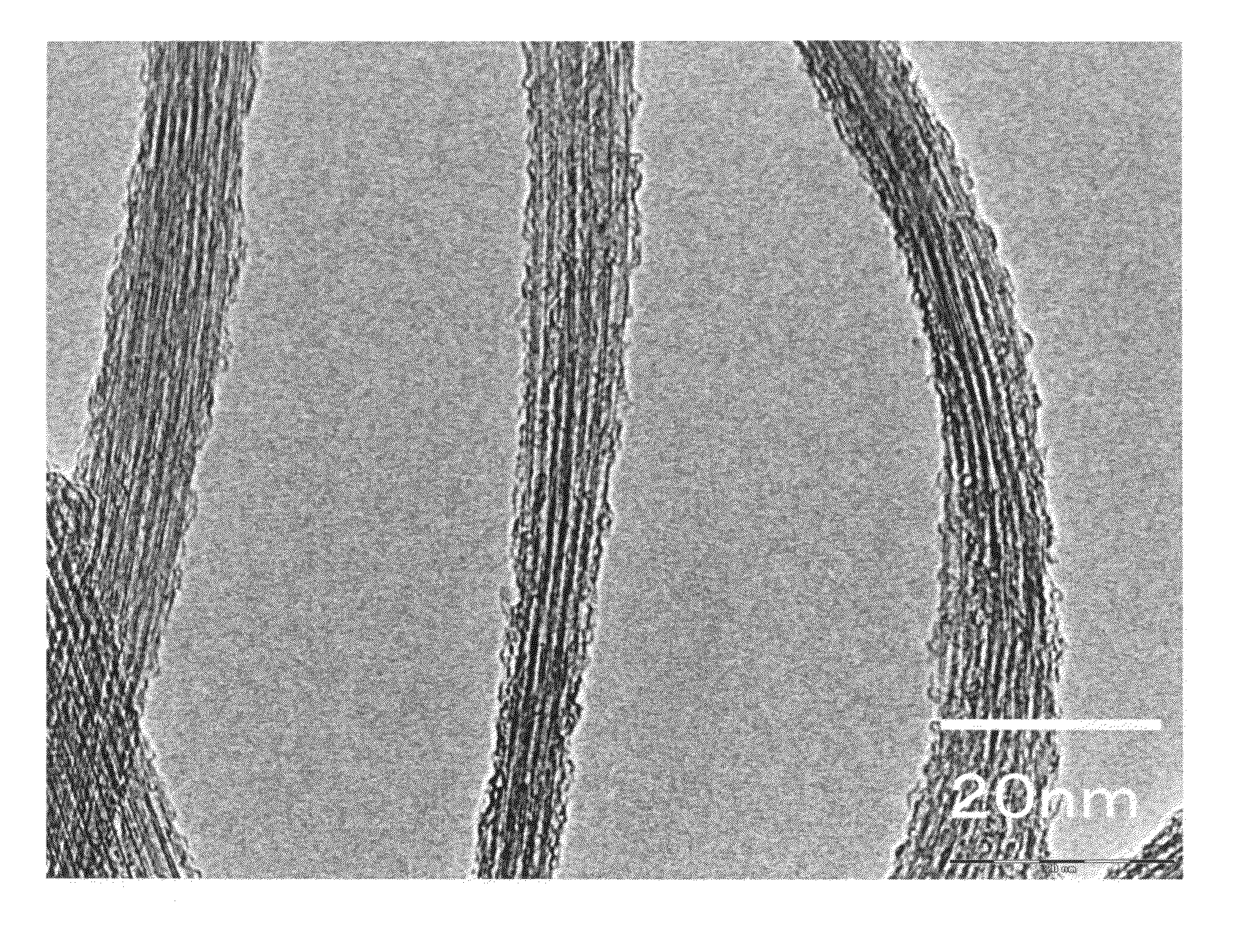
The present invention relates to an aggregate of carbon nanotubes that can be dispersed in a dispersant to form a high-concentration dispersion with good dispersibility. The carbon nanotubes have specific properties, such as being double-walled and having peaks in their Raman spectroscopic analysis. The aggregate of carbon nanotubes can be used to produce a transparent conductive film with high conductivity and excellent transmittance, as well as a field emission material with excellent electron discharge characteristics. The invention provides a solution for improving the dispersibility of carbon nanotubes in a dispersant.

Problems solved by technology

However, since these carbon nanotubes have a strong and very thick bundle structure, they cannot exhibit a nano-effect that each of the carbon nanotubes possesses, and it has been difficult to develop various applications thereof.
In particular, since the dispersion in a resin or solvent is very difficult, the present situation is that the development of various applications has been hindered.
In particular, it has been difficult to exhibit practical performance in applications as a transparent conductive film, molded article, membrane or the like using the carbon nanotubes.
However, such double-walled carbon nanotube forms, in the same manner as a single-walled carbon nanotube, a strong bundle through a hydrophobic interaction between tubes and interaction between π-electrons having difficulty in highly dispersing the carbon nanotube, thus it has been difficult to produce a transparent conductive film excellent in conductivity and transparency.Patent document 1: Japanese Unexamined Patent Publication No. 2005-343726Non-patent document 2: Nature, vol.

Method used

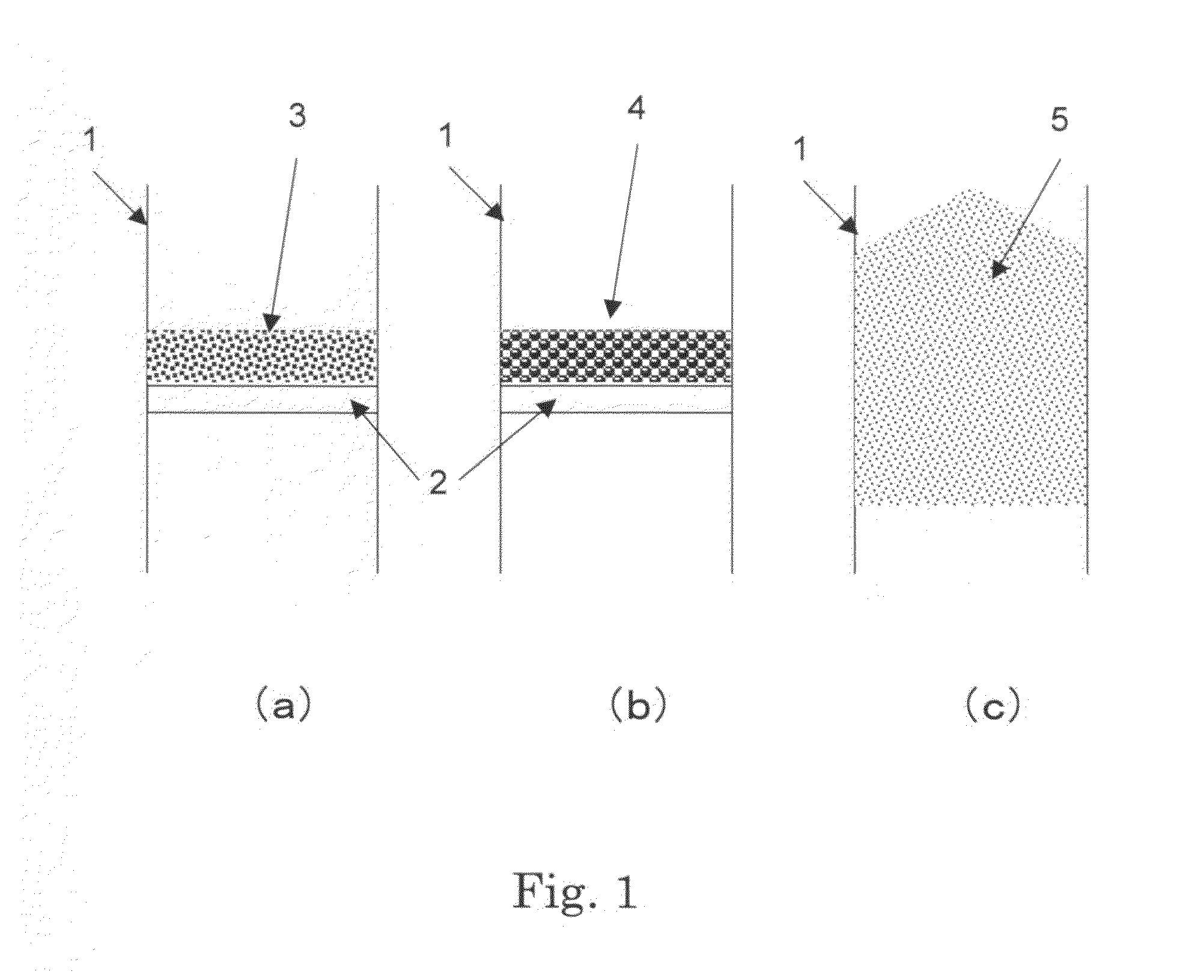

Image

  • Carbon nanotube assembly and electrically conductive film
  • Carbon nanotube assembly and electrically conductive film
  • Carbon nanotube assembly and electrically conductive film

Examples


example 1

Supporting Metal Salt on Light Magnesia

[0149]5 g of iron ammonium citrate (manufactured by Wako Pure Chemical Industries Ltd.) was dissolved in 250 mL of methanol (manufactured by Kanto Chemical Co., Ltd.). To this solution, 50 g of light magnesia (manufactured by Wako Pure Chemical Industries Ltd., bulk density was 0.16 g / mL) was added, treated for 60 minutes by an ultrasonic cleaner, and methanol was removed by drying while stirring at 40° C. to 60° C., thereby to obtain a solid catalyst that metal salt was supported on light magnesia powder.

[0150](Synthesis of Double-Walled Carbon Nanotube)

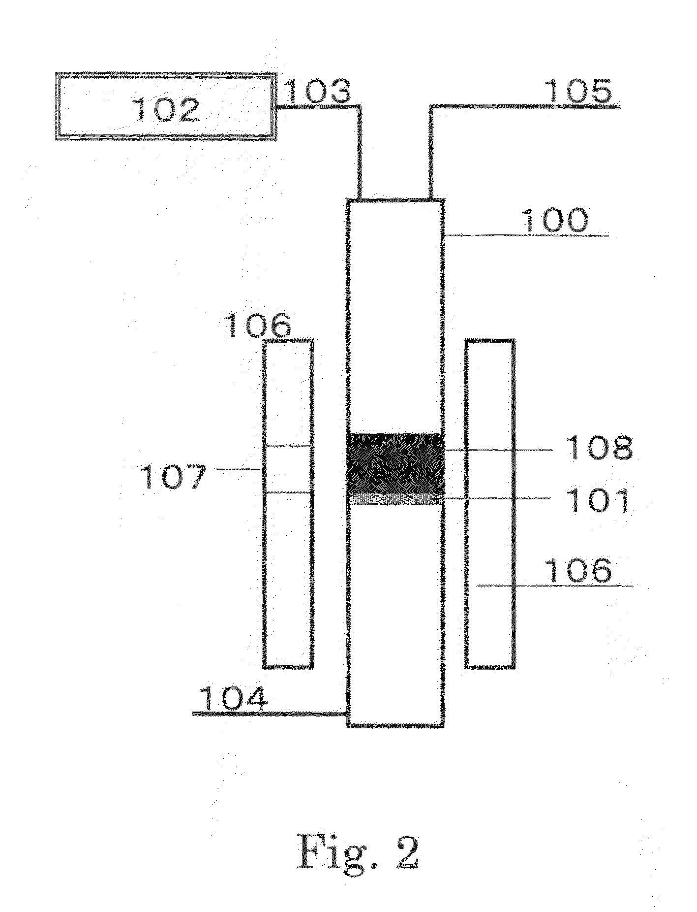
[0151]Carbon nanotubes were synthesized by a vertical reactor shown in FIG. 2.

[0152]A reactor 100 is a cylindrical quartz tube of 32 mm in inner diameter and 1200 mm in length. A quartz sintered plate 101 is equipped in the center part, an inert gas and raw gas supply line 104 is equipped in the bottom part of the quartz tube, and in the upper part thereof, a waste gas line 105, a sealed cataly...

example 2

Supporting Metal Salt on Light Magnesia

[0166]A solid catalyst was obtained by doing in the same manner as Example 1.

[0167](Synthesis of Double-Walled Carbon Nanotube)

[0168]On nonwoven fabric made of silica / alumina, 8.0 g of the solid catalyst prepared above was placed, and heated at 870° C. A quartz tube of 250 mm inner diameter equipped in a vertical direction inside a vertical reactor was introduced to the central part of a reaction tube of the vertical reactor equipped in the vertical direction of the reactor. Argon gas was supplied at 50 L / min for 5 minutes toward the upper direction of the quartz tube reactor from the bottom of the quartz tube reactor, flowed through a catalyst layer, then, methane gas and argon gas were introduced at 130 mL / min and 3.0 L / min, respectively for 30 minutes and flowed so as to be passed through the catalyst layer, both were contacted and reacted. Introduction of methane gas was stopped, after argon gas alone was flowed at 50 L / min for one minute, ...

example 3

Production of Field Electron Emission Source

[0179]In a beaker of 100 mL, 50 mg of the carbon nanotubes obtained in Example 1 that the catalyst was removed, and 100 mL of acetone were put, and irradiated by ultrasonic waves for 30 minutes, obtaining the dispersion liquid. The present dispersion liquid was put in a beaker in which a copper plate was put, left still for acetone to evaporate naturally, thereby to obtain a copper plate that carbon nanotubes were deposited on the surface.

[0180](Evaluation of Filed Electron Emission Capability)

[0181]The copper plate obtained can be used as a cathode of a field emission device. The copper plate that carbon nanotubes were deposited on the surface is used as a cathode electrode, and other copper plate is disposed as an anode electrode facing the above-described cathode electrode. This diode structural object is introduced to a chamber for evaluation, and field electron emission capability can be evaluated. The carbon nanotubes obtained in the...


PUM


Abstract

Provided is an aggregate of carbon nanotubes wherein a mixture of 10 mg of aggregate of carbon nanotubes, 30 mg of sodium polystyrene sulfonate and 10 mL of water is subjected to ultrasonic homogenizer treatment, subsequently subjected to centrifugal treatment at 20000 G, then 9 mL of supernatant is sampled, and the content of aggregate of carbon nanotubes in the supernatant is 0.6 mg / mL or more. The aggregate of carbon nanotubes of the present invention can provide a dispersion of an aggregate of carbon nanotubes having a high concentration through very good dispersibility.

Description

BACKGROUND OF THE INVENTION[0001]The present invention relates to an aggregate of carbon nanotubes and a method for producing the same. Further, it relates to a dispersion, a transparent conductive film and a field emission material using the aggregate of carbon nanotubes.BACKGROUND ART[0002]In 1991, carbon nanotubes were widely reported for the first time. A carbon nanotube has a tubular shape that substantially one face of graphite is wound, one wound in one layer is called a single-walled carbon nanotube, and one wound in multilayer is called a multi-walled carbon nanotube. Among multi-walled carbon nanotubes, in particular, one wound in two layers is called a double-walled carbon nanotube. Carbon nanotubes are expected to be used as a conductive material having excellent intrinsic electrical conductivity by themselves.[0003]As a method for producing carbon nanotubes, an arc layer, a catalyst chemical vapor deposition method has been known. Regarding the catalyst chemical vapor d...

Claims


Application Information

Patent Timeline
Patent Type & Authority Applications(United States)
IPC IPC(8): H01B1/04D01F9/12H01B1/24B82Y30/00B82Y40/00C09D7/61
CPCB82Y30/00C01B2202/30C01B31/0233C01B31/026C01B31/0273C01B2202/02C01B2202/04C01B2202/06C01B2202/28C01P2002/82C01P2004/04C01P2004/13C01P2004/133C08K3/04C09C1/44C09D5/24C09D7/1291H01B1/24C01B2202/20B82Y40/00C01B32/162C01B32/17C01B32/174C09D7/70C09D7/61C08K3/041
Inventor SATO, KENICHIYOSHIKAWA, MASAHITOIKEUCHI, SHUKO
Owner TORAY IND INC
Learn More