
Iron- and copper-comprising heterogeneous catalyst and process for preparing olefins by reacting carbon monoxide with hydrogen

a heterogeneous catalyst and iron oxide technology, applied in the field of iron and coppercomprising heterogeneous catalysts, can solve the problems of large amount of undesirable methane, loss of metal, and difficulty in reducing iron oxides required as catalyst starting materials, etc., to achieve the effect of reducing the surface area, reducing the amount of oxygen, and reducing the number of oxidized metals

Inactive Publication Date: 2011-05-12
BASF AG
View PDF14 Cites 5 Cited by
  • Summary
  • Abstract
  • Description
  • Claims
  • Application Information

AI Technical Summary

Benefits of technology

[0026]The catalyst should have an improved operation life and increased mechanical stability. The increased stability is, in particular, advantageous when the catalyst is used in a fluidized bed or in slurry reactors or else in bubble columns.
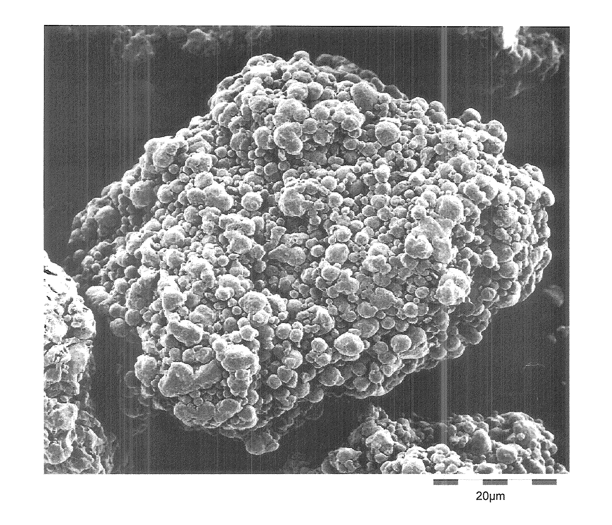
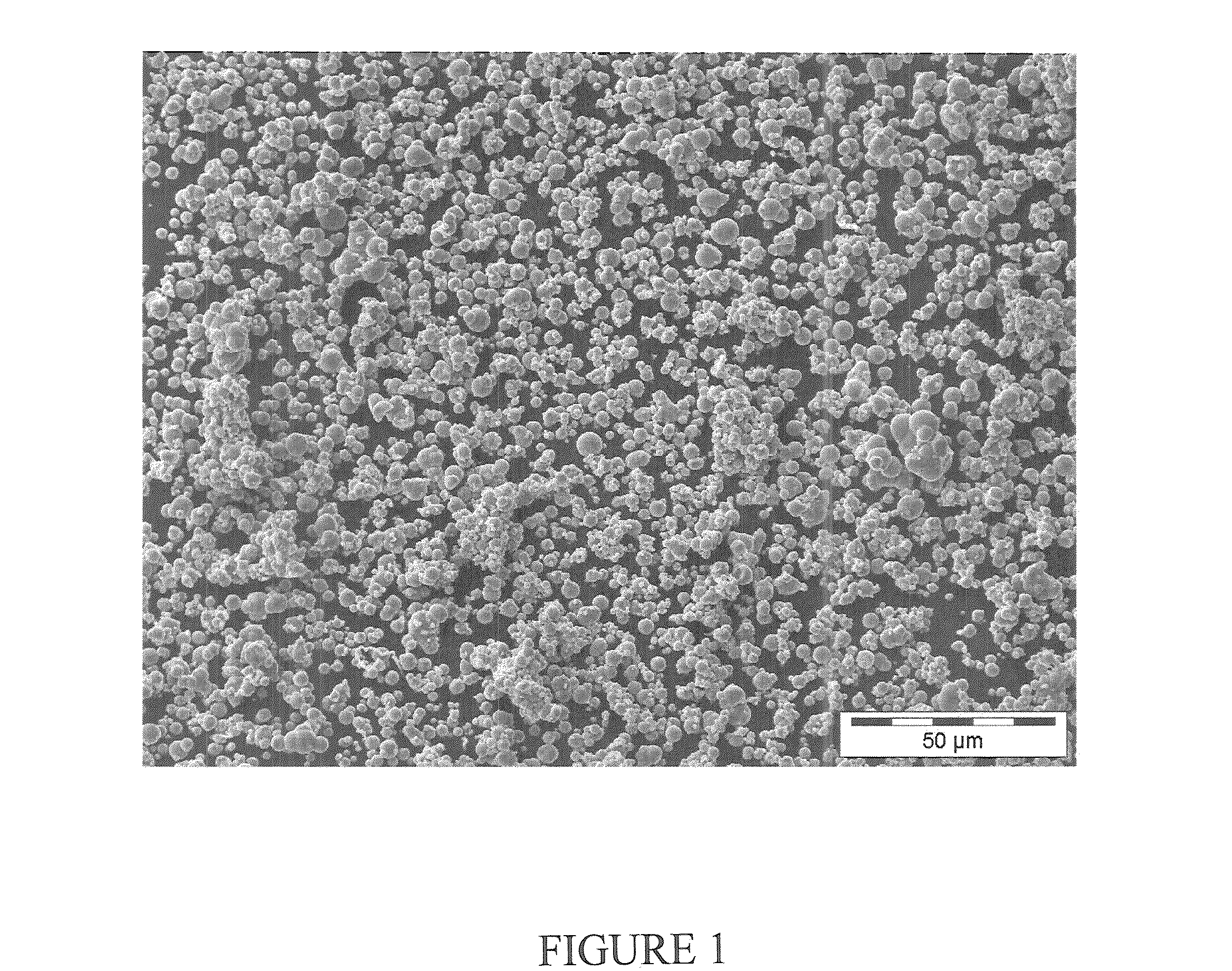
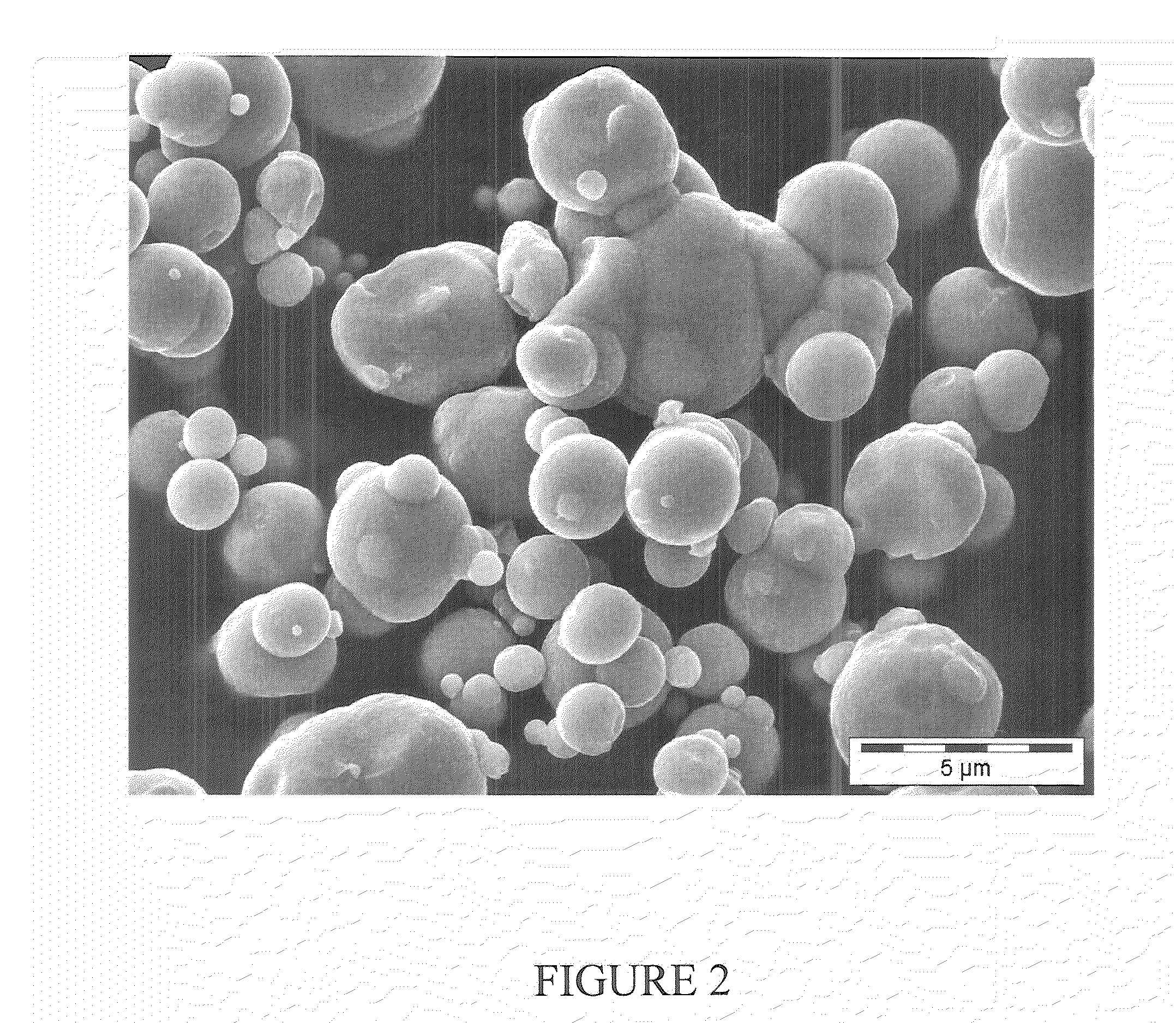
[0028]The metallic secondary particles formed with at least partial agglomeration in step II, particularly in a fluidizable fraction having particle diameters in the range 10-250 μm (see below), are ideal catalyst precursors for the synthesis of lower olefins from CO-rich synthesis gases because of their chemical composition. An additional advantage is the low surface area of the particles, which is preferably below 2 m2 / g (see below).
[0029]A particular advantage is the low oxygen content of the metallic secondary particles, as a result of which a reduction, and thus activation of the catalyst, is greatly simplified.

Problems solved by technology

The main problem here is the formation of large amounts of undesirable methane (CH4).
In addition, the iron oxides required as starting material for the catalyst are difficult to reduce.
The main disadvantage of these catalysts is that the active catalyst constituents can be volatile under the reaction conditions, which results in a loss of metal, and that they are toxic.

Method used


Image

  • Iron- and copper-comprising heterogeneous catalyst and process for preparing olefins by reacting carbon monoxide with hydrogen
  • Iron- and copper-comprising heterogeneous catalyst and process for preparing olefins by reacting carbon monoxide with hydrogen
  • Iron- and copper-comprising heterogeneous catalyst and process for preparing olefins by reacting carbon monoxide with hydrogen

Examples


example 1

Comparative Catalyst

Production of K- / Cu-Doped Carbonyl Iron Catalyst by Impregnation

[0095]100 g of carbonyl iron material having a particle size distribution of the secondary particles such that 90% by weight have a diameter in the range from 50 to 100 μm, see FIG. 4, were prepared from carbonyl iron powder type CN, BASF AG or now BASF SE, by treatment with hydrogen at least 300° C. and impregnated under ambient conditions (room temperature, atmospheric pressure) with 11 ml of aqueous potassium nitrate / copper nitrate solution. The aqueous potassium nitrate / copper nitrate solution was produced by dissolving 3.87 g of copper nitrate (×2.5 H2O, 99%, Riedel de Haen) and 0.66 g of potassium nitrate (99%, Riedel de Haen) in 11 ml of demineralized water. The impregnated catalyst was dried at 120° C. for 4 hours. The catalyst obtained comprised 0.23% by weight of K and 0.86% by weight of Cu.

example 2

According to the Invention

Production of K- / Cu-Doped Carbonyl Iron Catalyst (Mixed Oxide) by Impregnation

[0096]150 g of carbonyl iron material having a particle size distribution of the secondary particles such that 90% by weight have a diameter in the range from 50 to 100 μm, see FIG. 4, were prepared from carbonyl iron powder type CN, BASF AG or now BASF SE, by treatment with hydrogen at least 300° C. and passivated in a controlled manner by means of 5% by volume of air in nitrogen in a rotary bulb oven at a temperature up to not more than 35° C. The surface-passivated carbonyl iron powder was impregnated under ambient conditions (room temperature, atmospheric pressure) with 16.5 ml of aqueous potassium nitrate / copper nitrate solution. The aqueous potassium nitrate / copper nitrate solution was produced by dissolving 5.56 g of copper nitrate (×2.5 H2O, 99%, Riedel de Haen) and 0.79 g of potassium nitrate (99%, Riedel de Haen) in 16.5 ml of demineralized water. The impregnated catalys...

example 3

Filling of the Pores of Pure, Agglomerated Carbonyl Iron Powder (Secondary Particles) from Step II with Iron Pentacarbonyl According to Steps IIa and IIb

[0098]The amount of iron pentacarbonyl necessary for filling the pores having a diameter of, in particular, <4000 nm was determined by means of mercury porosimetry (DIN 66133).

[0099]200 ml of carbonyl iron material having a particle size distribution of the secondary particles such that 90% by weight have a diameter in the range from 50 to 100 μm, see FIG. 4, were prepared from carbonyl iron powder type CN, BASF AG or now BASF SE, by treatment with hydrogen at least 300° C. The carbonyl iron material was dried at 105° C. under an argon atmosphere in a stirred vessel for 5 hours. 10 ml of iron pentacarbonyl were then introduced. The vessel was subsequently heated to an internal temperature of about 165° C. The decomposition occurred at 165° C. with stirring of the particles. The reaction was complete when no iron pentacarbonyl or no ...


PUM

PropertyMeasurementUnit
Temperatureaaaaaaaaaa

Abstract

Iron- and copper-comprising heterogeneous catalyst and process for producing it, which comprises the following steps:I. thermal decomposition of gaseous iron pentacarbonyl to give carbonyl iron powder having spherical primary particles,II. treatment of carbonyl iron powder obtained in step I with hydrogen, resulting in the metallic spherical primary particles at least partly agglomerating,III. surface oxidation of the iron particles from step II (agglomerates=secondary particles, and also any primary particles still present) to form iron oxide,IV. contacting of the particles from step III with an aqueous solution of a copper compound,V. drying in the presence of oxygen and subsequent calcination in the absence of oxygen, resulting firstly in oxygen-comprising copper compounds on the particles and finally reaction of these with the iron oxide to form a mixed oxide of the formula CuxFe3-xO4, where 0<x≦1.Process for preparing olefins by reacting carbon monoxide with hydrogen in the presence of a catalyst, wherein the abovementioned iron- and copper-comprising heterogeneous catalyst is used as catalyst.

Description

CROSS-REFERENCE TO RELATED APPLICATIONS[0001]This application claims benefit of European patent application no. 09175224.6 filed Nov. 6, 2009, the contents of which are incorporated herein by reference in its entirety.FIELD OF THE INVENTION[0002]The present invention relates to an iron- and copper-comprising heterogeneous catalyst, a process for producing it and a process for preparing olefins by reacting carbon monoxide with hydrogen in the presence of the iron- and copper-comprising heterogeneous catalyst.BACKGROUND OF THE INVENTION[0003]It is known that lower olefins can be prepared from carbon monoxide (CO) and hydrogen (H2) over metal catalysts, e.g. iron or cobalt catalysts. Iron oxides are usually used as catalyst precursors. Such catalysts are described, for example, in U.S. Pat. No. 4,544,674, U.S. Pat. No. 5,100,856, U.S. Pat. No. 5,118,715, U.S. Pat. No. 5,248,701, US 2004 / 0127582 A1, H. P. Withers et al., Ind. Eng. Chem. Res. 1990, 29, pages 1807 to 1814, and M. E. Dry e...

Claims


Application Information

Patent Timeline
IPC IPC(8): B01J23/745B01J23/78B01J37/08B01J37/14B01J37/12C07C1/12
CPCB01J23/002C10G2400/20B01J23/72B01J23/745B01J23/78B01J35/023B01J37/0201B01J37/086B01J37/14B01J37/18B01J2523/00C07C1/044C07C2523/04C07C2523/72C07C2523/745C07C2523/885C10G2/332B01J23/005C07C11/02B01J2523/17B01J2523/842B01J35/40
Inventor STEINER, JOCHENBAY, KEREMWERNER, VERAAMANN, JURGENBUNZEL, STEFANMO BACHER, CLAUDIAMULLER, JOACHIMSCHWAB, EKKEHARDWEBER, MARKUS
Owner BASF AG
Learn More