Liquid-ejecting head, liquid-ejecting apparatus, piezoelectric element, and piezoelectric material
- Summary
- Abstract
- Description
- Claims
- Application Information
AI Technical Summary
Benefits of technology
Problems solved by technology
Method used
Image

Examples
first embodiment
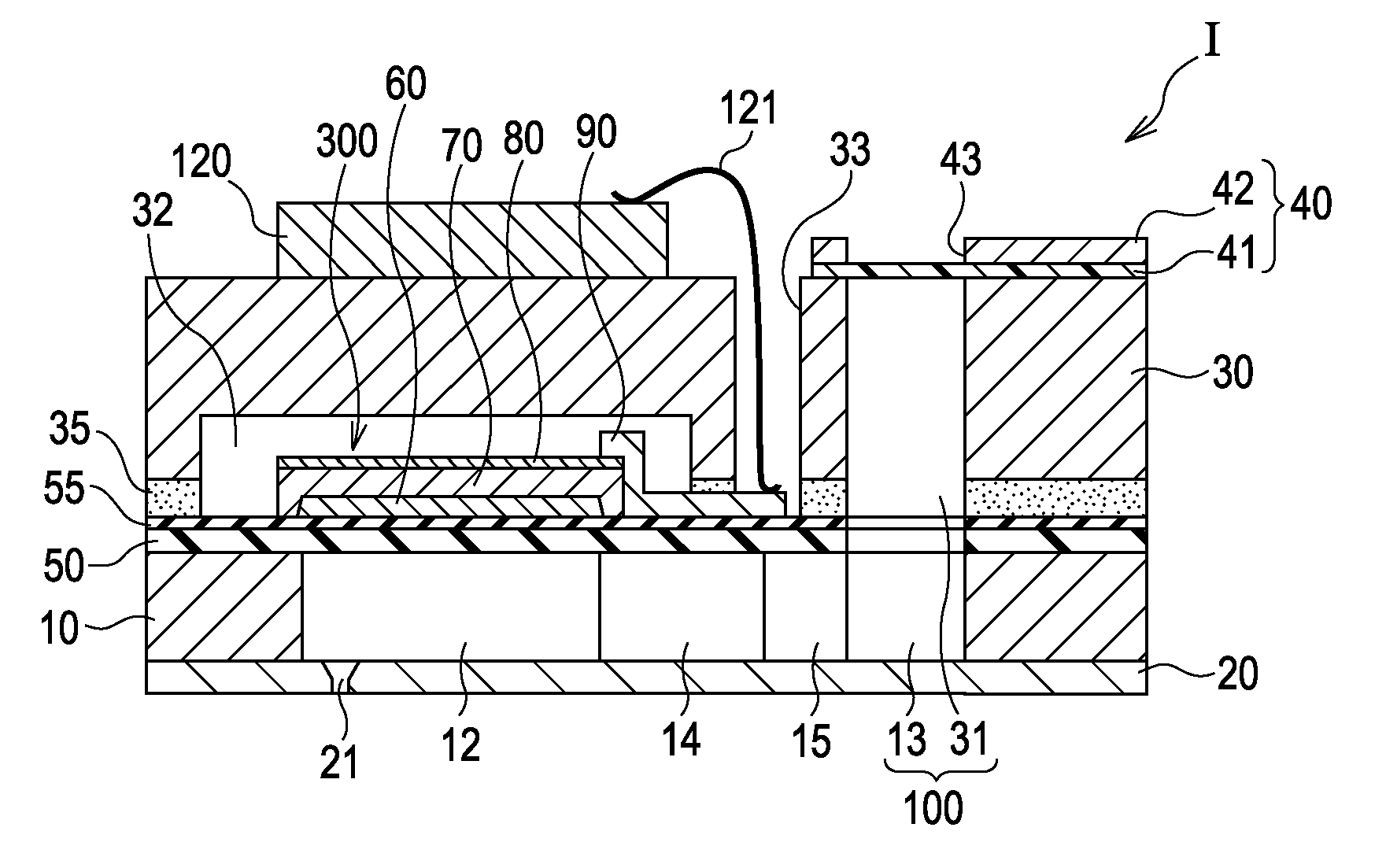
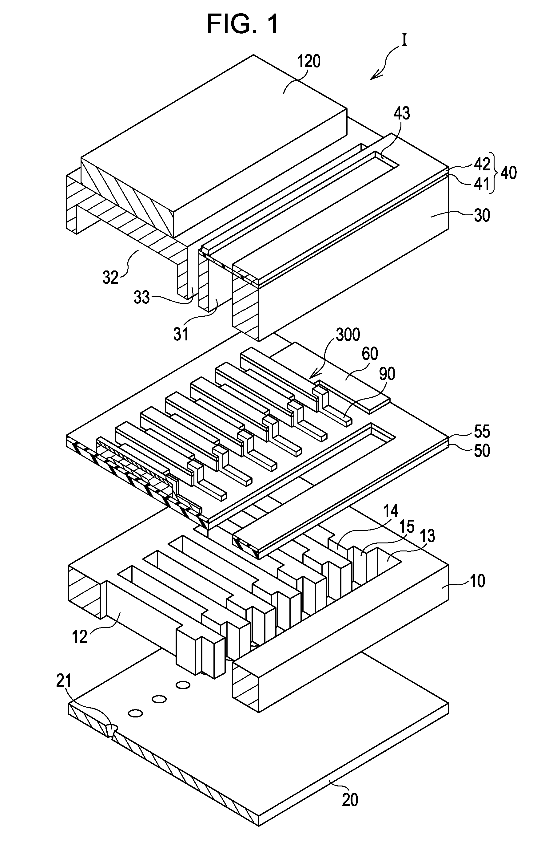
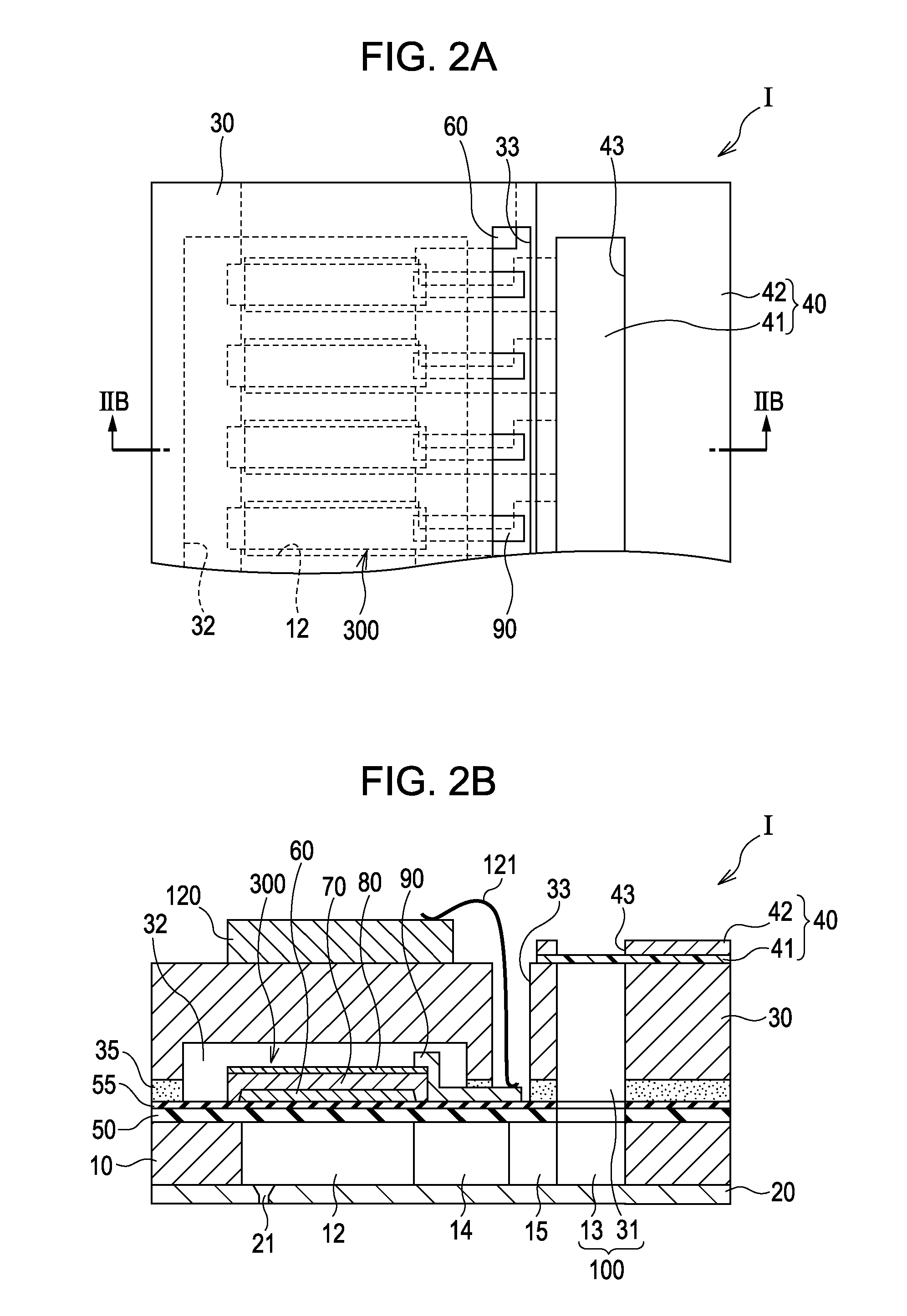
FIG. 1 is an exploded perspective view of an ink jet print head according to a first embodiment of the invention. This ink jet print head is an example of a liquid-ejecting head. FIG. 2A is a plan view of the ink jet print head according to the first embodiment. FIG. 2B is a cross-sectional view of the ink jet print head taken along the line IIB-IIB of FIG. 2A.
As illustrated in FIGS. 1 and 2, a flow-passage-forming substrate 10 according to the present embodiment is a silicon single crystal substrate. A silicon dioxide elastic film 50 is disposed on the flow-passage-forming substrate 10.
The flow-passage-forming substrate 10 includes a plurality of pressure-generating chambers 12 juxtaposed to each other in the width direction. The flow-passage-forming substrate 10 further includes a communication portion 13 outside the pressure-generating chambers 12 in the longitudinal direction. The communication portion 13 is in communication with the pressure-generating chambers 12 through corre...
example 1
A silicon dioxide film having a thickness of 400 nm was formed on a (100)-oriented silicon substrate by thermal oxidation. A titanium film having a thickness of 40 nm was formed on the silicon dioxide film by RF sputtering and was then thermally oxidized to form a titanium oxide film. A platinum film having a thickness of 150 nm was formed on the titanium oxide film by ion sputtering and vapor deposition to form a (111)-oriented first electrode 60.
A piezoelectric layer was formed on the first electrode by spin coating in the following manner. First, solutions of bismuth 2-ethylhexanoate, lanthanum 2-ethylhexanoate, iron 2-ethylhexanoate, or manganese 2-ethylhexanoate in xylene and octane were mixed at a predetermined ratio to prepare a precursor solution. The precursor solution was dropped on the substrate on which the titanium oxide film and the first electrode were formed, and the substrate was rotated at 1500 rpm to form a piezoelectric precursor film (a coating step). The precur...
examples 4 to 9
with 0.27≦x≦0.29 in the general formula (1) particularly had a consistent voltage at which electric-field-induced phase transition occurred. Examples 1 to 7 and Examples 10 and 11 with 0.01≦y≦0.05 in the general formula (1) had particularly high leakage resistance.
Comparative Examples 1 and 2, which had x and y outside the ranges of 0.21≦x≦0.38 and 0.01≦y≦0.09 in the general formula (1), were ferroelectric substances having a hysteresis including spontaneous polarization characteristic of a ferroelectric substance. Comparative Example 3 was a paraelectric material. Comparative Examples 4 to 6 could not be used as a piezoelectric material because of excessive leakage, as described above. Thus, all of these Comparative Examples were not an antiferroelectric substance that could undergo electric-field-induced phase transition.
PUM
 Abstract
Description
Claims
Application Information
 - R&D
- Intellectual Property
- Life Sciences
- Materials
- Tech Scout
- Unparalleled Data Quality
- Higher Quality Content
- 60% Fewer Hallucinations
Browse by: Latest US Patents, China's latest patents, Technical Efficacy Thesaurus, Application Domain, Technology Topic, Popular Technical Reports.
© 2025 PatSnap. All rights reserved.Legal|Privacy policy|Modern Slavery Act Transparency Statement|Sitemap|About US| Contact US: help@patsnap.com