
Colored golf ball

a golf ball and color technology, applied in the field of colored golf balls, can solve the problems of lack of elegant appearance and bright coloration, lack of luminosity of balls, and lack of color intensity, and achieve excellent spin performance and durability, excellent weather resistance, and outstanding visibility

Active Publication Date: 2011-03-24
BRIDGESTONE SPORTS
View PDF13 Cites 4 Cited by
  • Summary
  • Abstract
  • Description
  • Claims
  • Application Information

AI Technical Summary

Benefits of technology

[0038]A plurality of dimples are formed on the surface of the outermost cover layer. Because the dimples, by virtue of their diameter, number and depth, exert an influence on the appearance of the ball, it is preferable to form the dimples in a range that does not detract from the advantageous effects of the invention. More specifically, the number of such dimples, while not subject to any particular limitation, is preferably at least 250 but not more than 330. The dimples formed on the surface of the ball have a surface coverage (SR) which, while not subject to any particular limitation, is preferably at least 80%, and more preferably at least 90%, but preferably not more than 98%, and more preferably not more than 95%. For example, if the number of dimples is too large, when light strikes the ball, the visibility effect of the colored ball may diminish. That is, depending on the angle from which the ball is viewed, shadows will form at the bottoms of the dimples, which may cause the ball to appear darker. On the other hand, if the number of dimples is too small, good aerodynamic properties cannot be obtained when the ball is hit, as a result of which the ball may not travel the desired distance.
[0039]When a sphere having the above-described cover is Manufactured, a rubber composition composed primarily of polybutadiene or the like may be vulcanized under ordinary vulcanization conditions to form a crosslinked rubber molding (core), following which the cover (intermediate layer and outermost layer) may be successively molded over the core by a known process such as injection molding. Generally, a large number of dimples are formed on the surface of the outermost cover layer, the dimples being formed at the same time as formation of the outermost cover layer through the use of an outermost cover layer forming mold provided on the inner wall of the mold cavity thereof with a plurality of projections corresponding to the dimples.
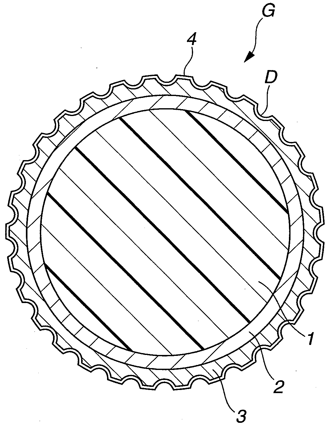
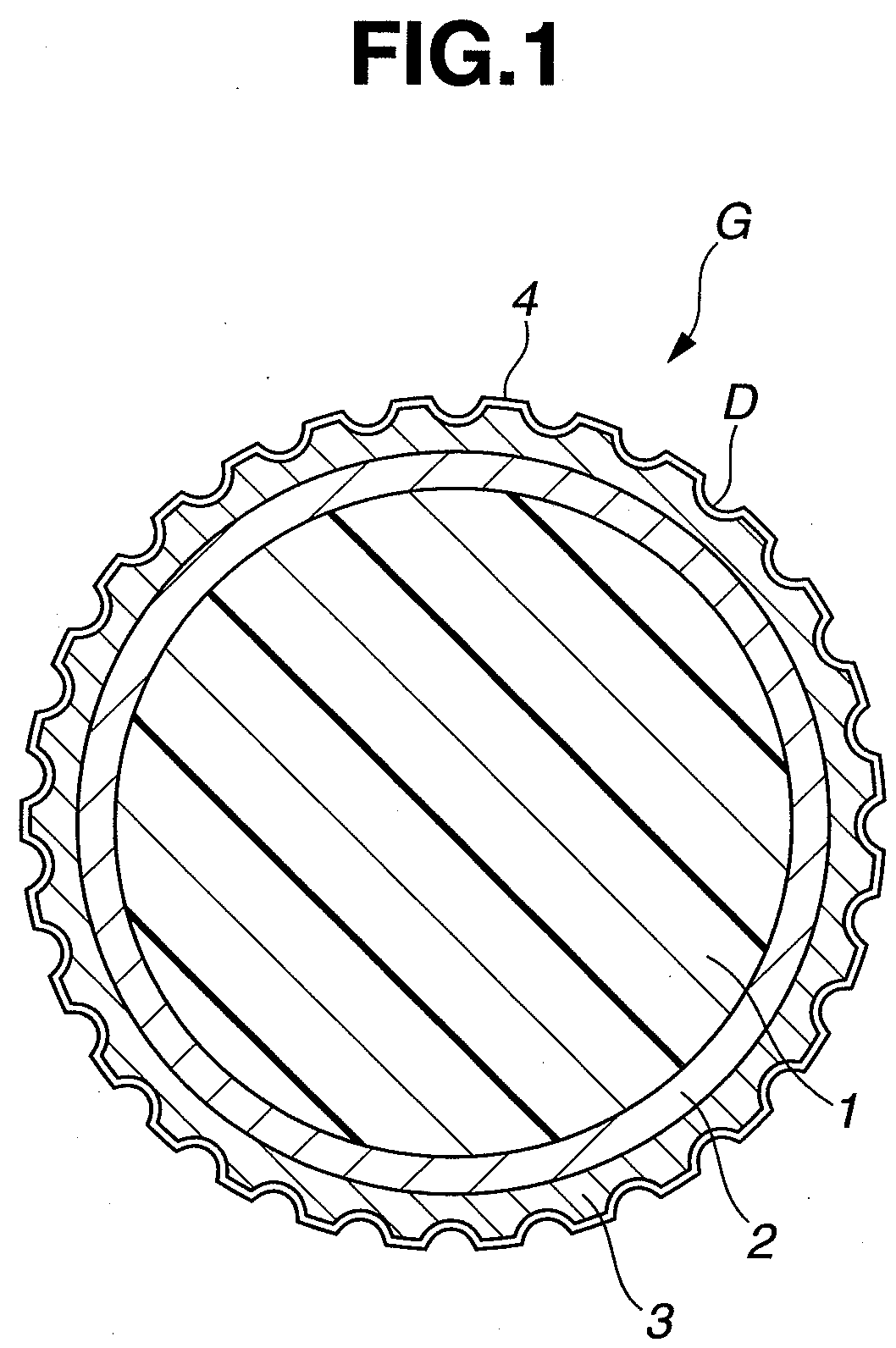
[0040]As shown in FIG. 1, the surface of-the outermost cover layer is covered by a layer of paint 4. This paint layer 4 has a thickness which, while not subject to any particular limitation, is preferably at least 5 μm, and more preferably at least 10 μm, but preferably not more than 20 μm, and more preferably not more than 16 μm. If the paint layer is too thin, the paint may have a poor durability. On the other hand, if the paint layer is too thick, the paint may have a large effect on the dimple shape, which may make it impossible to obtain flight properties according to design and may thus result in the ball traveling a less than desirable distance. Also, if the paint layer is too thick, the paint will have a tendency to peel, which may lower the durability of the ball to repeated impact.
[0041]It is preferable to use in the paint layer a paint which is commonly used to coat the surface of golf balls. Illustrative examples include urethane resin paints, acrylic resin paints, polyester resin paints, polyether resin paints, epoxy resin paints, modified forms thereof, or mixtures of any of the above. Of these, a two-component curing urethane resin paint obtained from a mixture of a polyisocyanate with a urethane resin, acrylic resin or polyester resin includes on the resin skeleton functional groups, particularly hydroxyl groups, capable of reacting with isocyanate groups is preferred. Examples of polyisocyanates that may be used include tolylene diisocyanate, diphenylmethane-4,4′-diisocyanate hexamethylene diisocyanate, isophorone diisocyanate, naphthalene diisocyanate, 1,4-phenylene diisocyanate, xylylene diisocyanate and hydrogenated xylylene diisocyanate, either singly or in modified forms as combinations thereof. The polyisocyanate component may generally take the form of an adduct, a biuret or an isocyanurate.
[0042]When the paint layer is formed by clear coating (coating with a clear paint), it is preferable to use a two-component curing urethane paint composed of a polyol component having hydroxyl groups and a polyisocyanate component having isocyanate groups.
[0043]Any known method used in the art may be employed as the coating method. For example, the ball may be perched on the tips of needles on a needle bed, and the entire ball coated with various paints by spraying. Prior to coating, any of a variety of techniques may be used to improve adhesion between the object to be coated and the layer of paint. Illustrative, non-limiting examples of such techniques include surface modification by plasma treatment or corona discharge treatment, and the application of a primer.

Problems solved by technology

Yet, few colored golf balls for the skilled golfer which take such factors into account, particularly colored golf balls with an outermost cover layer made of a polyurethane material, are available on the market.
Although this golf ball is more stylish than earlier colored golf balls, the colors within these ranges are pale colors, as a result of which the ball lacks an elegant appearance and a bright coloration.
However, given that the amount of fluorescent pigment included is somewhat high and that from 0.05 to 0.5 part by weight of titanium oxide is additionally combined therewith, the color tends to be too intense, in addition to which the ball is somewhat lacking in luminosity.
As a result, although this prior-art ball does have an excellent visibility, it falls a little short in terms of elegance.
This golf ball, although brightly colored and having an excellent weather resistance, exhibits a deep yellow hue, which is a color tone that lacks elegance.
However, this golf ball does not have a sufficient lightness, and thus falls somewhat short in terms of stylishness and visibility.
Although this golf ball does achieve a relatively vivid color tone, when a fluorescent dye is used, color changes such as fading tend to arise with the passage of time and exposure to the elements.

Method used


Image

  • Colored golf ball
  • Colored golf ball

Examples


examples

[0058]The following Examples of the invention and Comparative Examples are provided by way of illustration and not by way of limitation.

examples 1 to 13

, Comparative Examples 1 to 4

[0059]In each example and comparative example below, the rubber composition shown in Table 1 below was prepared, masticated in a kneader or roll mill, then fashioned into a core under vulcanization conditions of 155° C. and 20 minutes. Next, the resin composition shown in Table 2 was injection-molded around the core with an injection mold, thereby producing a sphere composed of the core encased by an intermediate layer. The sphere was then set in a different mold and an outermost cover layer material containing the specific amounts of fluorescent dye and titanium oxide shown in Table 3 was injection-molded. Next, the cover surface was plasma-treated, following which either (1) a non-yellowing urethane / acrylic resin-based paint was applied thereto by spray painting and dried, thereby coating the cover surface with a layer of clear paint having a thickness of about 15 μm, or (2) a specific amount of a pearlescent pigment was blended into a non-yellowing ur...


PUM

PropertyMeasurementUnit
diameteraaaaaaaaaa
thicknessaaaaaaaaaa
thicknessaaaaaaaaaa

Abstract

In a colored golf ball having a core, a cover of at least one layer encasing the core, and a layer of paint applied to a surface of an outermost layer of the cover, the outermost cover layer and / or the paint layer is colored with a fluorescent dye and titanium oxide, and the golf ball itself has a color tone which satisfies specific ranges in the Lab color system. The ball is endowed with an excellent spin performance and durability, an appearance characterized by outstanding visibility, stylishness and elegance, and an excellent weather resistance.

Description

CROSS-REFERENCE TO RELATED APPLICATION[0001]This application is a continuation-in-part of copending application Ser. No. 12 / 487,096 filed on Jun. 18, 2009, the entire contents of which are hereby incorporated by reference.BACKGROUND OF THE INVENTION[0002]The present invention relates to a colored golf ball having a fluorescent color. More specifically, the invention relates to a colored golf ball endowed with an excellent spin performance and durability, an appearance characterized by outstanding visibility, stylishness and elegance, and an excellent weather resistance.[0003]Lately, not all golf balls are white; a variety of colored balls have appeared on the market in response to the preferences of golfers. In particular, highly stylish colored golf balls and colored golf balls with an elegance appearance have been developed to suit the tastes of women golfers.[0004]At the same time, with the increasing versatility of golf balls in recent years, adopting a ball construction of at l...

Claims


Application Information

Patent Timeline
Patent Type & Authority Applications(United States)
IPC IPC(8): A63B37/14
CPCA63B37/0003A63B37/0024A63B43/008A63B37/12A63B37/0033
Inventor NAGASAWA, HIROYUKIMATSUDA, SATOSHI
Owner BRIDGESTONE SPORTS
Learn More