
Microfluidic device and method of using same

a microfluidic and microfluidic technology, applied in the field of microfluidic devices, can solve the problems of difficult to reliably detect rare sequences, limit the sensitivity of an assay in detecting rare molecular species, and high dynamic range of real-time monitoring of an exponential reaction, so as to reduce the volume of each assay

Inactive Publication Date: 2011-03-03
THE UNIV OF BRITISH COLUMBIA
View PDF43 Cites 124 Cited by
  • Summary
  • Abstract
  • Description
  • Claims
  • Application Information

AI Technical Summary

Benefits of technology

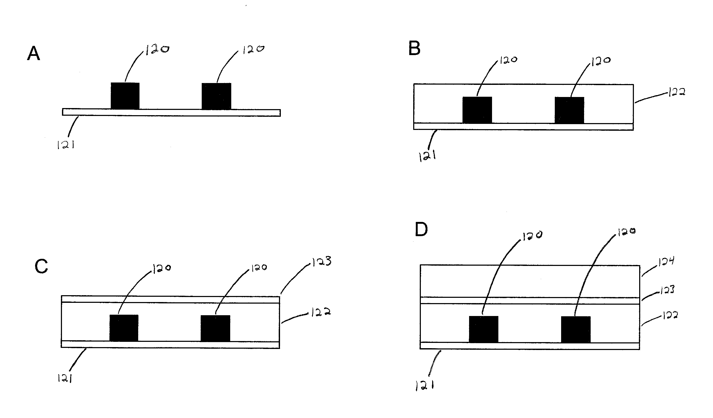
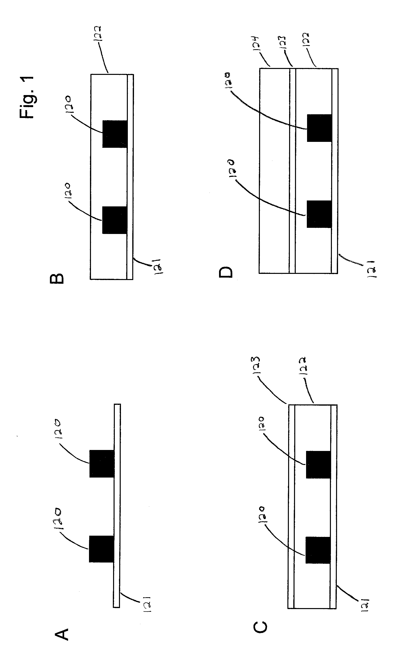
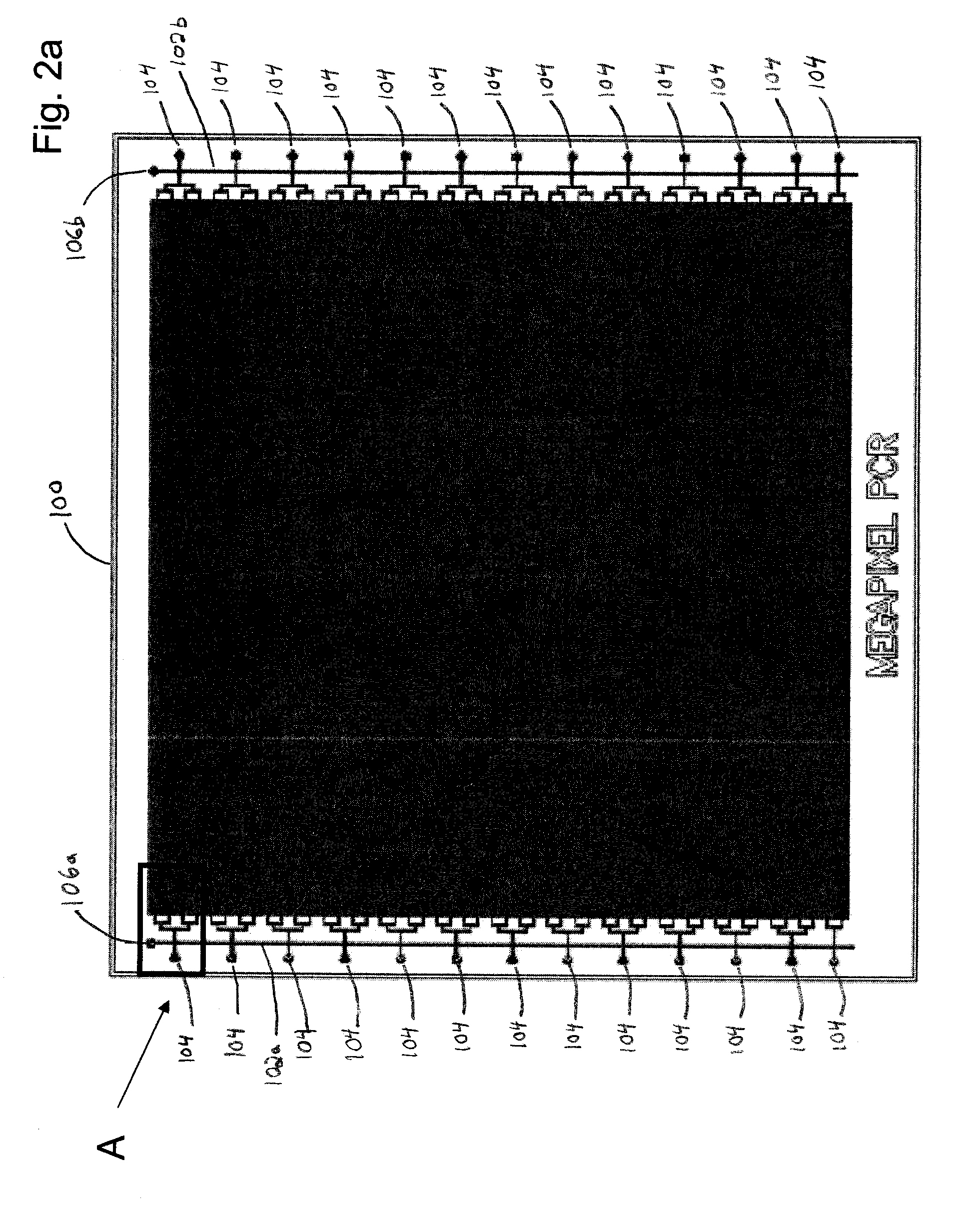
[0017]The present invention provides for a microfluidic device that provides an improvement in the density of reaction chambers by three orders of magnitude, achieving densities of up to about 10,000,000 reaction chambers per square inch (about 1.5×10⁶ / cm2) while reducing the volume of each assay by a commensurate amount. The device provides for assay compartmentalization in pL-volume emulsion arrays without the need for valves to segregate individual reaction chambers.
[0018]In accordance with one aspect of the present invention, there is provided a microfluidic device comprising a plurality of reaction chambers in fluid communication with a flow channel formed in an elastomeric substrate, a vapor barrier for preventing evaporation from the plurality of reaction chambers, and a continuous phase fluid for isolation of each of the plurality of reaction chambers.

Problems solved by technology

However, any non-specific amplification or contamination may lead to false positives, thereby making it very difficult to reliably detect rare sequences.
This is particularly true when target sequences are very similar to other species that may be present at higher levels, and thus may limit the sensitivity of an assay in detecting rare molecular species—the presence of a single nucleotide polymorphism in rare population of cancer cells may be invisible due to high background of normal molecules with nearly identical sequence.
Additionally, the real-time monitoring of an exponential reaction has high dynamic range but limited discriminatory power—differences below approximately 20% in the relative abundance of two sequences may be difficult to detect.
Digital PCR techniques provide for amplification of single molecules, however macroscopic implementations in microlitre volume reactors using conventional 96 and 384 well plates may have to overcome non-specific amplification, contamination, high reagent costs, and modest numbers of reactions.
This is not practical using existing methods.
The achievable density and minimum volume of PCR reactions in current microfluidic devices may be subject to practical limitations.
As the density of the array is increased, the volume of the individual reaction chambers is decreased, and valves may occupy too much space to be feasible.
Density and scale are particularly important in digital PCR since accurate measurements require the compartmentalization of a single sample into thousands to millions of individual reactions, making it expensive in terms of both device area and reagent consumption.
New methods for dramatically increasing assay density and reducing assay volume are therefore the central issue in realizing the full potential of this technique.
Thus, some processes that are carried out in PDMS-constructed microfluidic devices—particularly where elevated temperatures are required, such as PCR may suffer from drying out of the small aqueous reaction volume due to rapid evaporation, and the reactions may fail.
While this manages to reduce evaporation rates somewhat, the sample volume sizes that are able to be used successfully are still limited by evaporation even using this hydration.
This limits the ability of such systems to incorporate very small volume sample sizes (e.g. on the order of picolitres or smaller) that would enable high density arrays—and thus large sample numbers to improve the utility of the devices.

Method used


Image

  • Microfluidic device and method of using same
  • Microfluidic device and method of using same
  • Microfluidic device and method of using same

Examples


example 1

Amplification of Target Nucleic Acid in a Large Scale Microfluidic Emulsion Array

[0152]A device incorporating selected coverage by a vapour barrier was used to demonstrate the effects of the evaporation during a PCR experiment. A microfluidic device having the chamber geometry illustrated in FIG. 2d with a chamber density of 1 chamber / 1600 um2 was designed with 5 separate chamber arrays in order to test different samples on the same chip. The PCR solution was introduced into the device and compartmentalized as outlined in FIG. 3. A standard TaqMan assay for GAPDH along with TaqMan mastermix (Applied Biosystems) was used to monitor the progress of the reaction with a concentration of template DNA of about 10 copies per reaction chamber. The reaction was allowed to progress over 40 cycles and the end point picture is shown in FIG. 5.

[0153]The photomicrograph of FIG. 5 shows the results of one experiment. Reaction chambers with positive controls covered by the vapor barrier (positive c...

example 2

Single-Copy Amplification of Target DNA

[0155]By diluting the initial DNA (target nucleic acid) such that each reaction chamber contains only one molecule of DNA or none, it was possible to quantitatively identify the initial amount of DNA present in the sample. Only a reaction chamber with a copy of the target nucleic acid will provide a fluorescent signal for detection, as each chamber that has an optical signal indicates the presence of a target nucleic acid prior to PCR amplification.

[0156]As described, the microfluidic chip was loaded by connecting the fluid lines to a pressurized reservoir of PCR solution containing diluted DNA. After all the chambers were filled, Fluorinert™ oil was pressurized in the main flow lines thereby displacing the fluid everywhere except in the chambers, and the chip ready to be thermocycled. As the PCR reaction proceeds, images of the chip were taken at each cycle. It is therefore possible to see the DNA product (by means of the fluorescent signal) i...

example 3

Discrimination of Small Allelic Imbalances: Non-Invasive Detection of Fetal Trisomy 21

[0158]Minor imbalances in chromosome number were detected using digital PCR techniques employing the microfluidic arrays described herein. In order to determine a 1.5% increase in C21 in a sample, approximately 900,000 PCR reactions were required for 5 sigma certainty:

nC21-nC15=mɛ=kσ=knC21ɛ=1.5%nC21=NChambp(1+ɛ)nC21=m(2+ɛ)k=ɛNChambp(1+ɛ)2+ɛ=5⇒N=895,570chambers

[0159]M is the number of genomic equivalents (1 genome set=two of each chromosome). The sampling noise sigma is the square root of the number of chromosome 21. As discussed, if conventional PCR techniques are used, this number of reactions is prohibitively large and effectively impossible. Use of a microfluidics array comprising 106 reaction chambers condenses this number of reactions into a scale that is possible and effective.

[0160]Copy number of chromosomes 21 (C21) and 9 (C9) were determined using digital detection of the AIRE gene and ABL...


PUM

PropertyMeasurementUnit
Thicknessaaaaaaaaaa
Thicknessaaaaaaaaaa
Lengthaaaaaaaaaa

Abstract

A microfluidic device comprising a plurality of reaction chambers in fluid communication with a flow channel formed in an elastomeric substrate, a vapor barrier for preventing evaporation from the plurality of reaction chambers, and a continuous phase fluid for isolation of each of the plurality of reaction chambers.

Description

[0001]This application claims priority to U.S. Provisional Application 60 / 996,236 filed Nov. 7, 2007, which is herein incorporated by reference in its entirety.FIELD OF THE INVENTION[0002]The present invention relates to a microfluidic device.BACKGROUND OF THE INVENTION[0003]Current microfluidic devices (“chips”) and systems allow for semi-automated and automated manipulation of small volumes, generally a few nanolitres. The miniaturization of sample processing and assaying provides for both increased speed and sensitivity, as well as an economy of scale—less reagent, sample and space is required to run the assay and obtain the desired information, and the decreased handling of individual samples and reagents reduces opportunity for error. Microfluidic devices and systems have been adapted, or proposed for use with a variety of chemical and biochemical analyses including protein crystallography, cell free protein synthesis, gas chromatography, cell separation, electrophoresis, polym...

Claims


Application Information

Patent Timeline
IPC IPC(8): C12Q1/68C12M1/34B01L7/00
CPCB01J2219/00317B01L2400/0487B01J2219/00398B01J2219/00495B01J2219/00529B01J2219/00596B01J2219/00608B01J2219/00659B01J2219/00722B01L3/5025B01L3/5027B01L3/502723B01L3/50273B01L3/50851B01L7/52B01L2200/0605B01L2200/0621B01L2200/0642B01L2200/0689B01L2200/16B01L2300/0819B01L2300/0829B01L2300/0864B01L2300/123B01L2300/1805B01J2219/00396G06F3/017G06F3/04815G06F3/04842
Inventor HANSEN, CARL LARS GENGHISTROPINI, CAROLINA
Owner THE UNIV OF BRITISH COLUMBIA
Learn More