
Articles for high temperature service and methods for their manufacture

a technology of high temperature service and manufacturing methods, applied in the direction of silicates, carbides, superimposed coating processes, etc., can solve the problems of significant surface recession and mass loss of silicon-bearing materials, significant degradation of material structure, and unacceptably high recession rates, etc., to achieve the effect of improving the capability

Active Publication Date: 2011-03-03
GENERAL ELECTRIC CO
View PDF9 Cites 41 Cited by
  • Summary
  • Abstract
  • Description
  • Claims
  • Application Information

AI Technical Summary

Benefits of technology

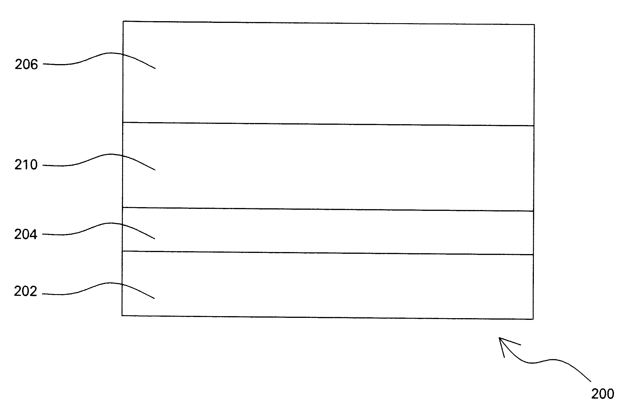
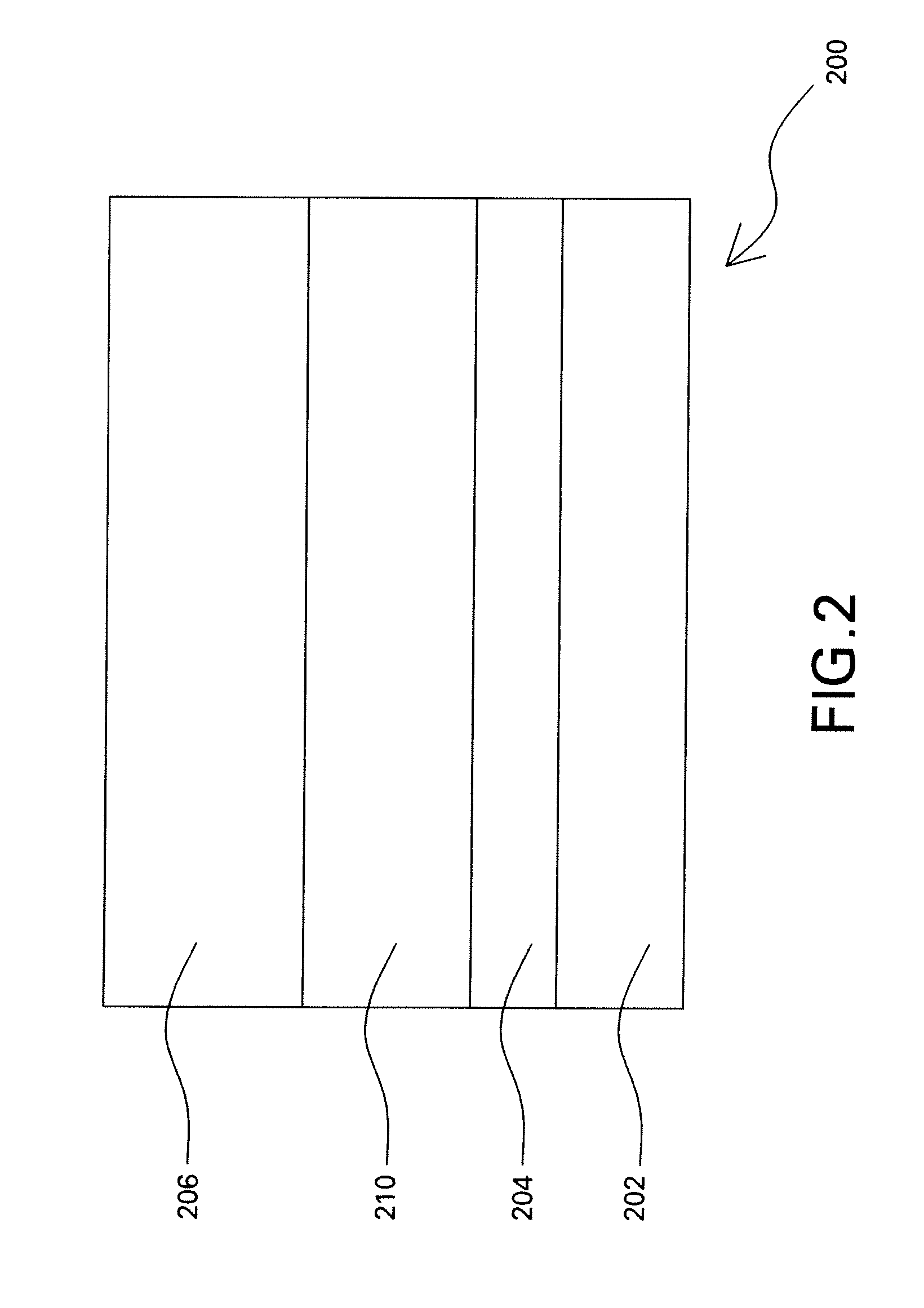
"The present invention provides an article comprising a substrate and a self-sealing and substantially hermetic sealing layer disposed over the substrate. The sealing layer comprises an alkaline-earth aluminosilicate. The substrate may be any high-temperature material, including silicon-bearing ceramics and ceramic matrix composites. The article also includes an intermediate layer disposed between the sealing layer and the bondcoat, and a topcoat disposed over the sealing layer. The sealing layer has good barrier properties with respect to silica. The method for making the article involves heating the sealing layer to a sealing temperature and maintaining it for an effective time to form a substantially hermetic layer. The technical effect of this invention is to provide an article with improved barrier properties and a sealing layer that can effectively protect the substrate from corrosion and damage."

Problems solved by technology

However, the environments characteristic of these applications often contain reactive species, such as water vapor, which at high temperatures may cause significant degradation of the material structure.
For example, water vapor has been shown to cause significant surface recession and mass loss in silicon-bearing materials.
The water vapor reacts with the structural material at high temperatures to form volatile silicon-containing species, often resulting in unacceptably high recession rates.
However, ceramic coatings processed by plasma spraying often contain undesirable open porosity in the form of a network of fine cracks (“microcracks”) intercepting otherwise closed pores and voids.
For EBC applications, open porosity in the coating can be detrimental.
However, extension of the hot deposition process technique to large components is challenging, owing to the high substrate temperatures and the constraints associated with manipulation of the parts and the coating hardware.
Although this method is relatively easy to implement, it may require multiple impregnation-burnout cycles to achieve coating permeability improvements, and in certain cases may provide an incompletely hermetic coating structure.

Method used


Image

  • Articles for high temperature service and methods for their manufacture
  • Articles for high temperature service and methods for their manufacture
  • Articles for high temperature service and methods for their manufacture

Examples


example 1

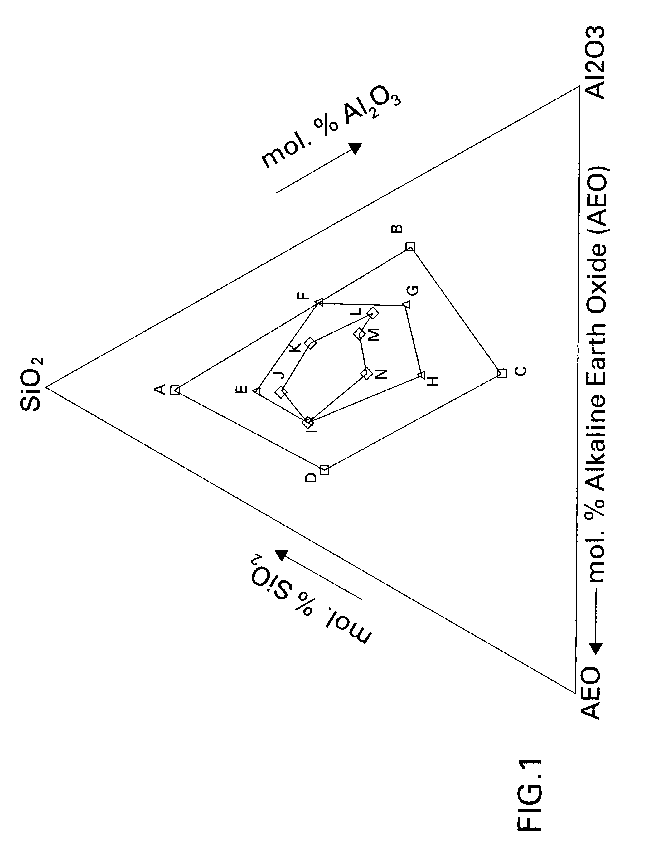
[0031]A silicon carbide ceramic matrix composite substrate was coated by plasma spraying the substrate with a silicon bondcoat and then a layer of yttrium disilicate. Then an alkaline earth aluminosilicate sealing layer having the following composition: 50 mole % SiO2-25 mole % Al2O3-25 mole % alkaline earth oxide, where the alkaline earth oxide in this case was a mixture of BaO and SrO, was deposited on the yttrium disilicate layer. The substrate was sectioned and metallographically examined after spraying, and a network of fine cracks was observed throughout the alkaline-earth aluminosilicate layer. The coated substrate was then heat treated in air for 30 minutes at 950 degrees Celsius followed by 30 minutes at 1020 degrees Celsius. Another specimen having the same set of coatings was heated to 1000 degrees Celsius at a slow heating rate and was removed from the furnace immediately. Each of the heat treated specimens described above was sectioned and metallographically examined, a...

example 2

[0032]A multi-layered coating assembly comprising a first layer of yttrium disilicate (about 100 micrometers nominal thickness), a second layer of the alkaline earth aluminosilicate described in Example 1 (about 75-100 micrometers nominal thickness), and a third layer of yttrium disilicate (about 100 micrometers nominal thickness) was fabricated using plasma spray deposition. Air permeability tests showed that the permeability to air of the multi-layered coating assembly after heat treatment for 10 hours at 1315 degrees Celsius was at least a factor of ten lower than that measured in the as-sprayed condition, demonstrating an improvement in coating hermeticity.

example 3

[0033]A multi-layered coating assembly comprising a first layer of yttrium disilicate, a second layer of the alkaline earth aluminosilicate described in Example 1, a third layer of yttrium disilicate, and a fourth layer of yttrium monosilicate was fabricated using plasma spray deposition. The first through third layers were nominally about 75-125 micrometers thick, and the monosilicate layer was nominally about 50-75 micrometers thick. Air permeability tests showed that the permeability to air of the multi-layer assembly after heat treatment (same heat treatment as in Example 1) was at least a factor of ten lower than that measured in the as-sprayed condition, demonstrating an improvement in coating hermeticity.


PUM

PropertyMeasurementUnit
temperatureaaaaaaaaaa
sealing temperatureaaaaaaaaaa

Abstract

An article for use in aggressive environments is presented. In one embodiment, the article comprises a substrate and a self-sealing and substantially hermetic sealing layer comprising an alkaline-earth aluminosilicate disposed over the bondcoat. The substrate may be any high-temperature material, including, for instance, silicon-bearing ceramics and ceramic matrix composites. A method for making such articles is also presented. The method comprises providing a substrate; disposing a self-sealing alkaline-earth aluminosilicate layer over the substrate; and heating the sealing layer to a sealing temperature at which at least a portion of the sealing layer will flow.

Description

STATEMENT REGARDING FEDERALLY SPONSORED RESEARCH & DEVELOPMENT[0001]This invention was made with U.S. Government support under contract number DE-FC26-05NT42643 awarded by the Department of Energy. The Government has certain rights in the invention.BACKGROUND[0002]This invention relates to high-temperature machine components. More particularly, this invention relates to coating systems for protecting machine components from exposure to high-temperature environments. This invention also relates to methods for protecting articles.[0003]High-temperature materials, such as, for example, ceramics, alloys, and intermetallics, offer attractive properties for use in structures designed for service at high temperatures in such applications as gas turbine engines, heat exchangers, and internal combustion engines, for example. However, the environments characteristic of these applications often contain reactive species, such as water vapor, which at high temperatures may cause significant degr...

Claims


Application Information

Patent Timeline
Patent Type & Authority Applications(United States)
IPC IPC(8): B32B9/04C01B33/26C09D1/00B05D3/02
CPCC01B31/36C23C28/042C04B41/89C09D1/02C23C26/00C23C30/00C04B41/52C09D5/00B32B9/04C04B41/4527C04B41/5096C04B41/5024C04B41/0072C01B32/956
Inventor SARRAFI-NOUR, REZAMESCHTER, PETER JOELJOHNSON, CURTIS ALANLUTHRA, KRISHAN LALROSENZWEIG, LARRY STEVEN
Owner GENERAL ELECTRIC CO
Learn More