
Design of a wet/wet amplified differential pressure sensor based on silicon piezoresistive technology

a technology of silicon piezoresistive technology and differential pressure sensor, applied in the field of pressure sensors, can solve the problems of no wet differential amplified pressure sensor, moisture damage to wire bonds,

Inactive Publication Date: 2007-01-16
HONEYWELL INT INC
View PDF9 Cites 119 Cited by
  • Summary
  • Abstract
  • Description
  • Claims
  • Application Information

AI Technical Summary

Benefits of technology

[0012]e) a pressure cap on the elastomeric media seal, which pressure cap is attached to the housing such that the pressure cap and the housing together form a hermetic seal which prevents the escape or entry of a gas through the hermetic seal; said pressure cap further having a port therethrough for admitting a gas under pressure into the first cavity;
[0021]e) attaching a pressure cap to the housing over the elastomeric seal, such that the pressure cap and the housing together form a hermetic seal which prevents the escape or entry of a gas through the hermetic seal; said pressure cap further having a port therethrough for admitting a gas under pressure into the first cavity;
[0031]e) a pressure cap on the elastomeric media seal, which pressure cap is attached to the housing such that the pressure cap and the housing together form a hermetic seal which prevents the escape or entry of a gas through the hermetic seal; said pressure cap further having a port therethrough for admitting a gas under pressure into the first cavity;

Problems solved by technology

This moisture damages the wire bonds that are used for bonding the sensor and piezoresistors that are doped on the surface of the sensor.
However, there is also a great need in the art for measuring pressures in wet media directly as epoxy interferes with the measurements.
Currently there is no wet differential amplified pressure sensor based on piezoresistive sensing technology with a surface mounted technology (SMT) package.
None of these employ a pressure sensor positioned in one compartment of a housing and a signal amplifier positioned in a separated compartment of the housing so that the signal amplifier is separated from a relatively harsh, wet, pressure sensing environment.

Method used


Image

  • Design of a wet/wet amplified differential pressure sensor based on silicon piezoresistive technology
  • Design of a wet/wet amplified differential pressure sensor based on silicon piezoresistive technology
  • Design of a wet/wet amplified differential pressure sensor based on silicon piezoresistive technology

Examples


Embodiment Construction

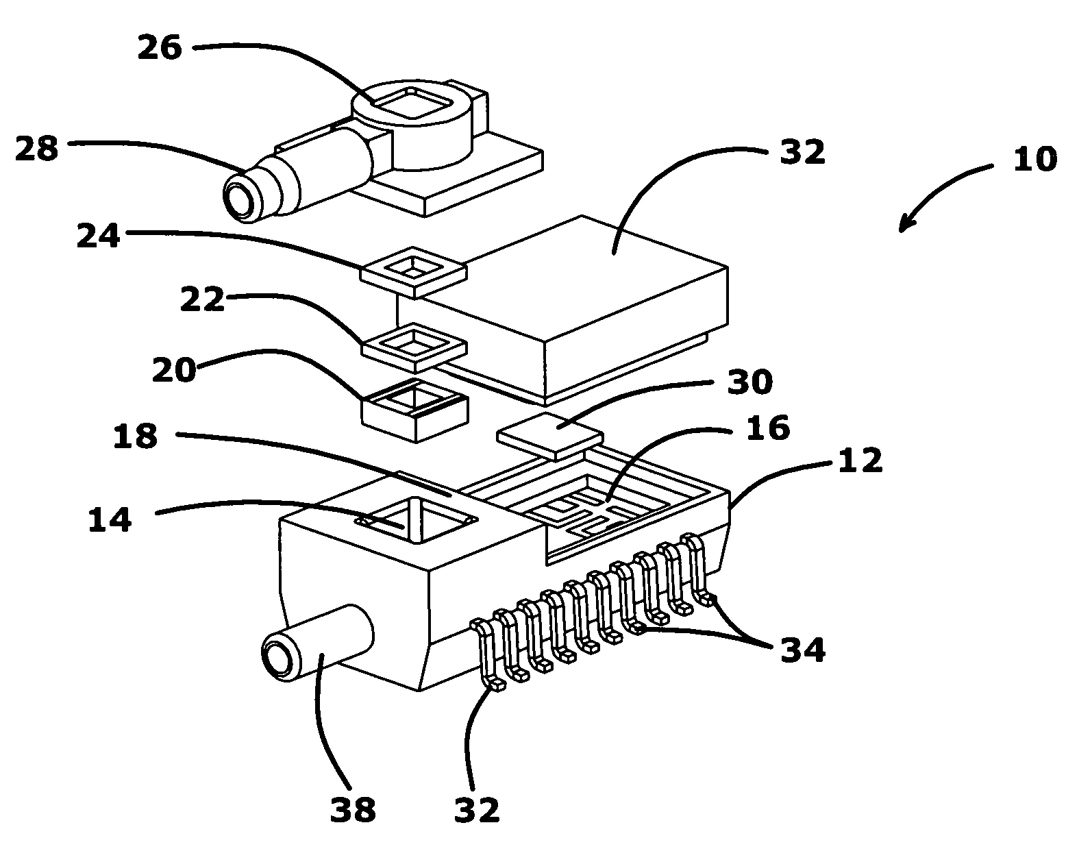
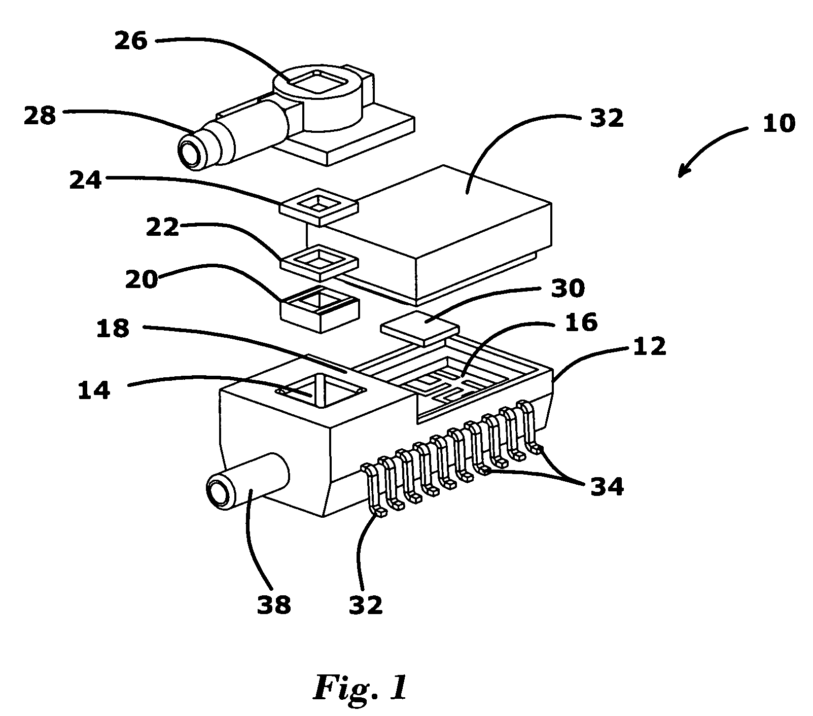
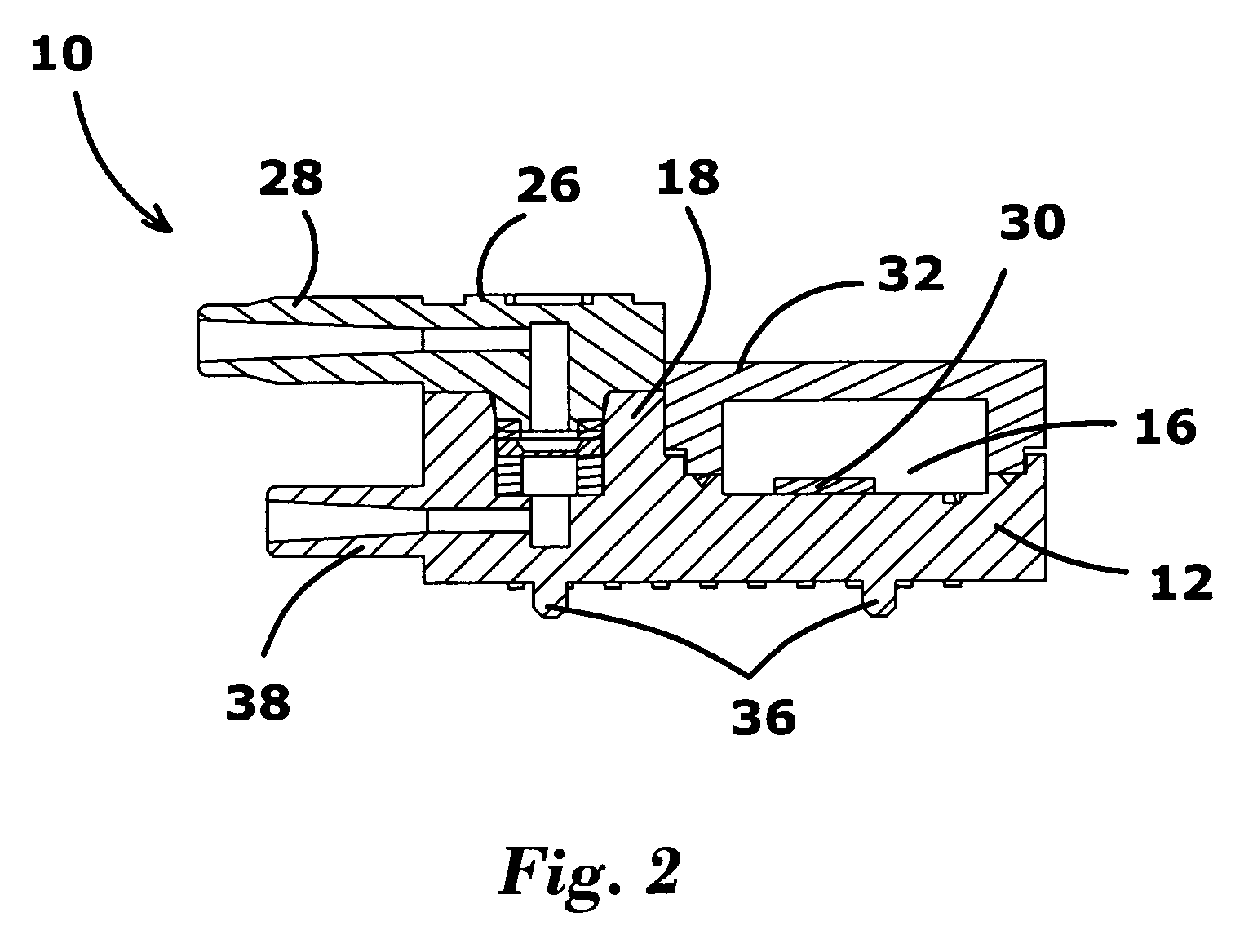
[0045]Referring to FIG. 1 and FIG. 2, there is shown an embodiment of the sensor package 10 according to the invention. The sensor package is shown to have a housing 12 having a first cavity 14 and a second cavity 16 within the housing 12. A wall member 18 separates the first cavity 14 and the second cavity 16. Sequentially sandwiched within the first cavity 14 is an electrically conductive elastomeric pad 20 positioned within the first cavity, a pressure sensor 22 electrically conductive elastomeric pad 20 and an elastomeric media seal 24, positioned on the pressure sensor 22. Then a pressure cap 26 covers the elastomeric media seal. The pressure cap 26 is attached to the housing 12 such that the pressure cap 26 and the housing 12 together with the electrically conductive elastomeric pad 20, a pressure sensor 22 and elastomeric media seal 24, form a hermetic seal which prevents the escape or entry of a gas through the hermetic seal. In the embodiment shown in FIG. 1, the pressure c...


PUM


Abstract

The invention provides pressure sensors for use in wet environments. A pressure sensor package according to the invention has a housing having a pair of cavities separated by a wall member. Sequentially contained within one cavity is a conductive elastomeric seal pad, a pressure sensor and an elastomeric media seal. A pressure cap is attached to the housing such that the pressure cap and the housing together form a hermetic seal. The pressure cap has a port for admitting a gas under pressure into the first cavity. A signal amplifier is positioned within the second cavity and a cover encloses the signal amplifier within the second cavity. An electrical connector through the wall member forms an electrical connection between the pressure sensor and the signal amplifier. A lead frame extends through the housing and forms electrical connections with the pressure sensor and the signal amplifier.

Description

BACKGROUND OF THE INVENTION[0001]1. Field of the Invention[0002]The present invention relates to pressure sensors or more particularly to pressure sensors for use in wet environments.[0003]2. Description of the Related Art[0004]In wet applications, a pressure sensor comes into contact with fluids and gases having high moisture content. This moisture damages the wire bonds that are used for bonding the sensor and piezoresistors that are doped on the surface of the sensor. As a result, silicon piezoresistive sensing technology has heretofore only been used directly for dry media applications and has been used by protecting it with epoxy for wet applications. However, there is also a great need in the art for measuring pressures in wet media directly as epoxy interferes with the measurements. There is also a need for an amplified pressure sensor for such applications. Some applications additionally need to have signal conditioning / signal amplification incorporated in sensor packages. M...

Claims


Application Information

Patent Timeline
IPC IPC(8): G01L9/00
CPCG01L19/0084G01L19/148G01L19/143G01L9/00G01L19/00
Inventor SELVAN, THIRUMANI A.SHENOY, GURURAJ U.SADASIVAN, SARAVANANMUNIRAJU, RAGHAVENDRA
Owner HONEYWELL INT INC
Learn More