
Porous multilayer filter and method for producing same

a multi-layer filter and porous technology, applied in the field of porous multi-layer filters, can solve the problems of affecting the yield of products, reducing the productivity of products, and difficult to balance the treatment rate and particle retention efficiency, and achieves stable permeability, high flow rate, and preservation

Inactive Publication Date: 2011-03-03
SUMITOMO ELECTRIC FINE POLYMER INC
View PDF3 Cites 29 Cited by
  • Summary
  • Abstract
  • Description
  • Claims
  • Application Information

AI Technical Summary

Benefits of technology

[0022]However, the first invention and the second invention have other characteristics in common, such as in the formation of a multilayer structure composed of the filtration layer and the support layer. In the hydrophilic case, as described above, shrinkage during drying poses a problem. In the case where hydrophilization treatment is not performed, there is a possibility that, when a high pressure is applied, the membrane may be damaged if the membrane is composed of the filtration layer alone. When the thickness of the filtration layer is increased in order to suppress the problems, it becomes difficult to increase the flow rate. In each of the first invention and the second invention, by using a common configuration, such as formation of a multilayer structure composed of the filtration layer and the support layer, it is possible to increase the flow rate while trapping ultrafine particles at a high retention efficiency.
[0088]Therefore, the filters can be suitably used as gas / liquid filters for microfiltration used in manufacturing processes in the semiconductor and liquid crystal fields and food / medicine field, in which higher retention efficiency of ultrafine particles and a high treatment rate are required.

Problems solved by technology

These filters for microfiltration are mainly used as filters for treating air in clean rooms and as filters for filtration of chemical solutions, and their performance affects the yield of products.
However, when filters with small pore sizes are used in order to secure high particle retention efficiency, permeability, i.e., the treatment rate for chemical solutions or air, decreases, resulting in a decrease in productivity of products.
Thus, in the conventional filters for microfiltration, it is very difficult to balance the treatment rate and particle retention efficiency.
However, in the porous body of PTL 1, a radiation irradiation step is essential, thus increasing costs, which is a problem.
Therefore, a considerable time is required for filtration.
As described above, it is difficult to obtain a filter which has both a high particle retention ratio and permeability.
Furthermore, since PTFE porous bodies are hydrophobic, water does not easily permeate into the porous bodies, which is a problem.
However, in the case where the hydrophilic coating film is formed on the surface of a PTFE porous body or the like having a thickness of 20 μm or less, when the hydrophilic polymer of the hydrophilic coating film dries and shrinks, the PTFE porous body succumbs to the strength of the coating film and shrinks.
As a result, the porosity decreases and the flow rate of permeation decreases, which is a problem.
On the other hand, in the case where a hydrophilic filtration membrane is produced by setting the thickness of a PTFE porous body to be large in advance and maintaining the thickness of a hydrophilic coating film to 20 μm or less, the large thickness increases resistance, and therefore, it is not possible to increase the flow rate, which is a problem.

Method used


Image

  • Porous multilayer filter and method for producing same
  • Porous multilayer filter and method for producing same
  • Porous multilayer filter and method for producing same

Examples


examples of first embodiment

[0135]First to fifth porous multilayer filters including filtration layers 3 having varying bubble points were fabricated as examples.

example 1

[0136]With respect to a main body of a filtration layer, 18 parts by mass of a liquid lubricant (Supersol FP-25 manufactured by Idemitsu Kosan Co., Ltd: (constituent: naphtha)) was added and mixed to 100 parts by mass of PTFE fine powder (PTFE 601 A manufactured by DuPont). The resulting mixture was subjected to compression molding in a molding machine to form a block-like shaped body.

[0137]Next, the block-like shaped body was continuously extruded into a sheet-like shape. The sheet-like shaped body was passed through pressure rolls, further passed through heating rolls (130° C. to 220° C.) in order to remove the liquid lubricant, and wound up on a roll to obtain a sheet of 300 μm.

[0138]Next, with respect to a sheet for the main body of the filtration layer, after stretching at a magnification of 2 times in the longitudinal direction (machine direction) at a roll temperature of 250° C. to 280° C., stretching is further performed at a magnification of 4 times under the same temperatu...

example 2

[0144]In the filtration layer 3, the amount of addition of the liquid lubricant was changed to 20 parts by mass relative to the resin 601A (manufactured by DuPont). The longitudinal stretch magnification was set at 8 times, and the lateral stretch magnification was set at 30 times. The bubble point of the filtration layer 3 was set at 250 kPa, and the size of target particles to be trapped was set at 0.05 μm. Otherwise, the structure was the same as that of Example 1.


PUM

PropertyMeasurementUnit
porosityaaaaaaaaaa
pore sizeaaaaaaaaaa
thicknessaaaaaaaaaa

Abstract

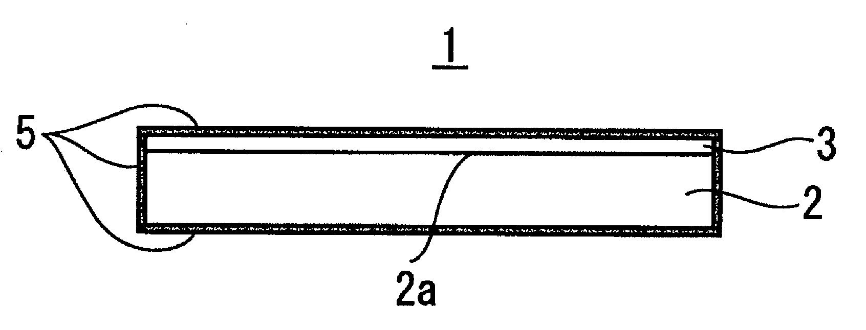
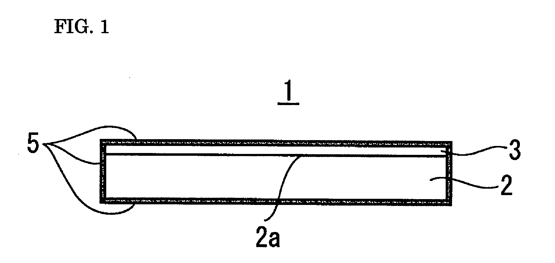
Provided is a porous multilayer filter which can trap ultrafme particles and in which permeability is high and treatment can be performed at a high flow rate. A porous multilayer filter is characterized by including a support layer 2 composed of a porous expanded PTFE sheet, and a filtration layer 3 composed of a porous expanded PTFE sheet which is different from that of the support layer 2, wherein at least a liquid-to-be-treated inflow surface of the filtration layer 3 is subjected to hydrophilization treatment, the filtration layer 3 and the support layer 2 are fusion-bonded to each other at a boundary therebetween to form a multilayer structure, pores of the support layer 2 three-dimensionally communicate with pores of the filtration layer 3, and pores surrounded by a fibril skeleton of the filtration layer 3 are smaller than pores of the support layer 2.

Description

TECHNICAL FIELD[0001]The present invention relates to a porous multilayer filter, and more particularly, relates to a filter for microfiltration capable of filtering ultrafine particles at a high flow rate.BACKGROUND ART[0002]Polytetrafluoroethylene (hereinafter, referred to as “PTFE”) porous filters have characteristics inherent in PTFE, such as high heat resistance, chemical stability, weatherability, noncombustibility, high strength, non-adhesiveness, and a low coefficient of friction, as well as characteristics possessed by porous bodies, such as flexibility, liquid permeability, particle retention efficiency, and a low dielectric constant, and have been conventionally used in a variety of fields, such as in liquid / gas filters for microfiltration (membrane filters), wire coating materials, and breather valves (air vents).[0003]In recent years, because of excellent characteristics, such as high chemical stability, PTFE porous filters have been widely used, in particular, as filte...

Claims


Application Information

Patent Timeline
Patent Type & Authority Applications(United States)
IPC IPC(8): B32B3/26B29C65/02B32B7/02
CPCB01D61/147B32B2327/18B01D69/02B01D69/12B01D71/36B01D2323/02B01D2323/30B01D2325/02B01D2325/20B01D2325/36B29C67/04B29K2027/18B29K2105/04B32B5/18B32B27/28B32B37/04B32B38/0012B32B2305/026B32B2307/728B01D67/0093B32B5/16B32B5/22B32B5/30B32B7/02B32B27/08B32B27/14B32B27/322B32B2255/04B32B2255/10B32B2255/26B32B2260/025B32B2260/046B32B2264/0257B32B2307/306B32B2307/546B32B2307/712B32B2307/714B32B2307/724B32B2307/726B32B2307/73Y10T428/249953B01D69/1213B01D2323/58B01D2325/04B01D2325/02833B01D2325/02834B01D2325/0281B01D69/1214B01D67/00933
Inventor UNO, ATSUSHIFUNATSU, HAJIMETSUJIWAKI, HIROYUKI
Owner SUMITOMO ELECTRIC FINE POLYMER INC
Learn More