Pipeline inspection apparatus and method

Active Publication Date: 2011-02-24
PII LIMITED
View PDF2 Cites 25 Cited by
  • Summary
  • Abstract
  • Description
  • Claims
  • Application Information

AI Technical Summary

Benefits of technology

[0013]Both the symmetric Lamb wave mode and the shear wave mode may have a wavelength similar to the pipe wall thickness. Waves having these wavelengths are long enough to propagate unattenuated over large sectors of steel pipeline but short enough to allow useful circumferential and axial position resolution needed for comparison between the two mode types. In addition, the horizontally polarised shear mode may have a wavelength arranged to permit efficient generation of the fundamental wave mode and at least one higher shear wave mode. The higher shear wave mode may provide further options for comparing the responses of the different modes to the defect. This may increase discrimination accuracy.
[0014]In use the wave modes may be excited in the pipe wall in a manner to reduce or minimise interference or cross-talk. Each mode may be transmitted at separate times, or may be transmitted simultaneously from sensors which are physically displaced to avoid significant interference.
[0016]The sensor module may have one or more pairs of each EMAT sensor type, the members of each pair being separated from each other around the pipeline vehicle circumference. The separation is arranged so that the members of each pair may lie on opposite sides of a defect. In this embodiment signals of each wave mode transmitted past the defect may be obtained in addition to echo signals from the defect itself to improve the accuracy of the comparison between echo signals of each wave mode. For example, the detected transmitted signals may be used to compensate for variations in wall thickness and the like, which may affect each wave mode differently.
[0017]Thus, each pair of sensors may be configured to transmit signals therebetween to allow regular calibration of the sensor performance throughout the inspection record and facilitate the comparison of signal amplitudes that permits defect discrimination.

Problems solved by technology

In gas filled pipelines it is difficult to use conventional piezo-electric transducers because the gaseous pipeline product is not an efficient coupling medium for introducing ultrasound into the pipe wall.
Breaks in the homogeneity of this metal grid (e.g. defects such as cracks) will result in reflections of the sound wave.
However, the spatial resolution of the inspection is usually lower than for conventional (e.g. piezo-electric) sensors operating in pipelines which carry liquid.
A consequence of this is that EMAT sensors, which are able to detect reliably the presence of pipe wall defects, are comparatively poor at providing sufficient information to identify the type of pipe wall defect.

Method used


Image

  • Pipeline inspection apparatus and method
  • Pipeline inspection apparatus and method
  • Pipeline inspection apparatus and method

Examples


Embodiment Construction

Further Options and Preferences

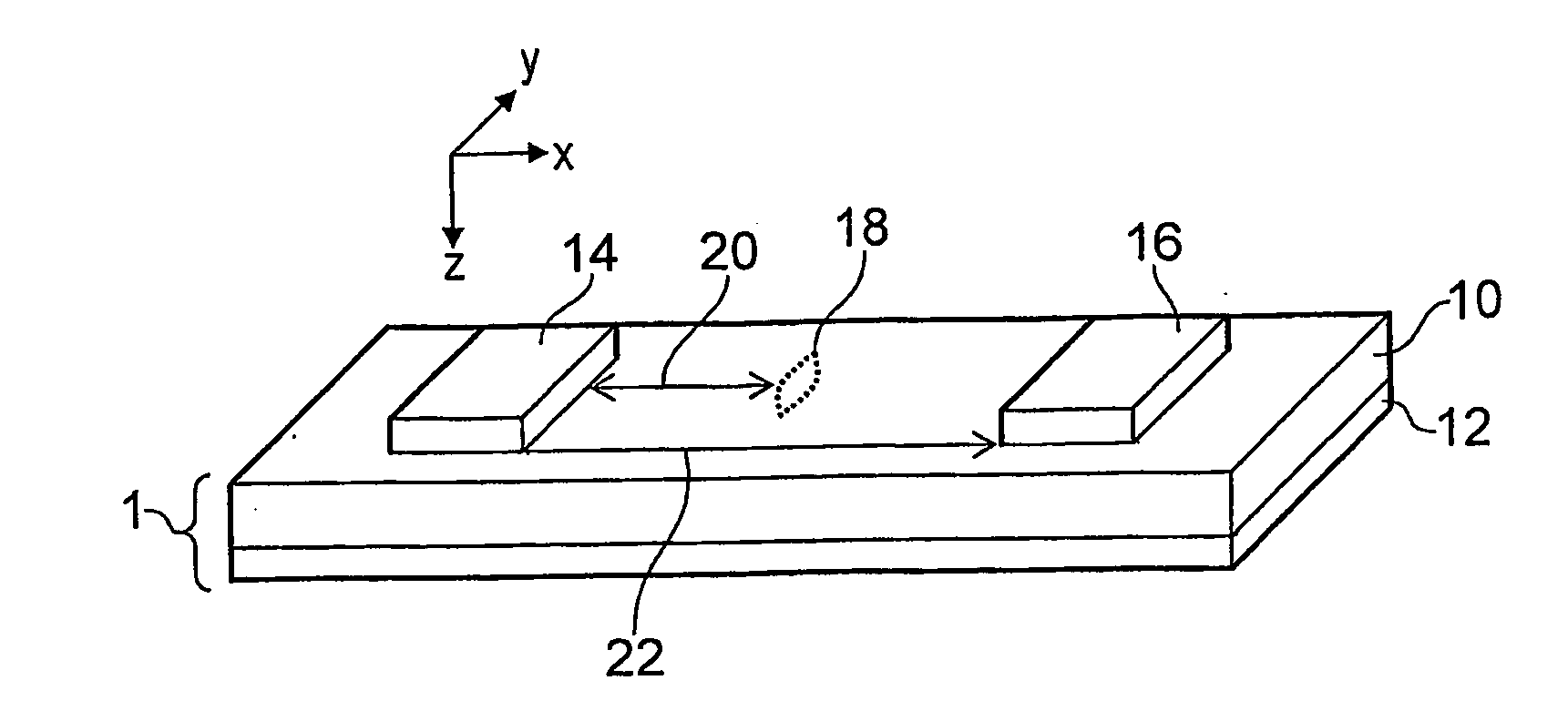
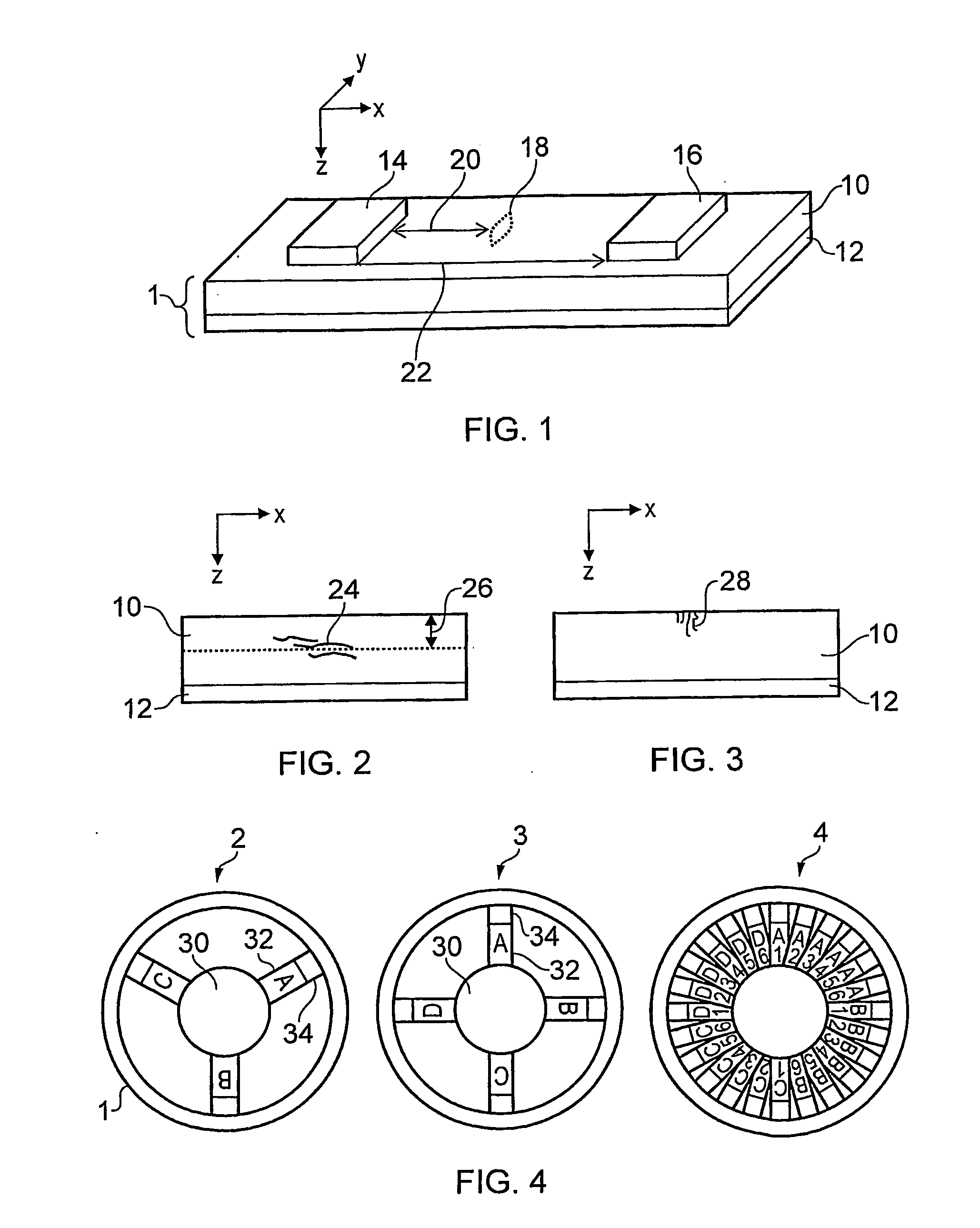
[0026]FIG. 1 is a schematic diagram of a pipe wall 1 that is useful to illustrate the principles of the invention. The pipe wall 1 comprises a metal e.g. steel layer 10 which has a protective outer coating 12 e.g. or bitumen or a polymer material bounded to it. In FIG. 1 the pipe wall is shown to be flat. In reality it is curved e.g. to form a tube with an axis extending in either the x or the y direction.

[0027]The inspection apparatus of the invention may have two sensors 14, 16 arranged to contact the inner surface of the metal layer 10 at circumferentially spaced locations (i.e. locations separately in the x direction). Each of the sensors 14, 16 may be positioned at a distance from a defect 18 to be tested. The sensors 14, 16 are EMATs arranged to generate guided acoustic (ultrasonic) waves in the metal layer 10. To enable the type of defect to be determined, the sensors 14, 16 are arranged to generate two different types of acoustic wave. This may...


PUM


Abstract

Ultrasonic pipeline inspection apparatus which utilises two different wave modes (e.g. a horizontally polarised shear mode and a symmetric Lamb wave mode) to discriminate different defect types by comparing corresponding signals collected from defects. EMATs may detect the signals. The detected amplitudes of the collected signals from both wave modes are compared to calculate a ratio, which may be compared with a distribution of ratio values for known defects to evaluate the type of defect detected. The apparatus may be a sensor module mountable on a pipeline vehicle and having a plurality of sensors distributed around its periphery.

Description

TECHNICAL FIELD[0001]The invention relates to apparatus for and methods of inspecting the integrity of pipelines. For example, it may relate to the internal inspection of operational pipelines using pipeline vehicles.BACKGROUND TO THE INVENTION[0002]To maintain the integrity of pipelines, it is known to employ inspection vehicles that travel internally to the pipe recording information about the quality of the pipe wall. The majority of these inspection vehicles use ultrasonic or magnetic sensors to carry out the inspection.[0003]The preferred technology for crack detection is ultrasonic inspection, and in pipelines carrying liquids a vehicle-based inspection system can use the liquid as a coupling medium to assist conventional piezo-electric sensors. These sensors are capable of carrying out well-established inspection techniques leading to high resolution of defects and discrimination of defects based on through-wall positional resolution. In gas filled pipelines it is difficult t...

Claims


Application Information

Patent Timeline
IPC IPC(8): G01N29/04
CPCF16L2101/30G01N29/2412G01N29/48G01N2291/0422G01N2291/2672G01N2291/044G01N2291/105G01N2291/2636G01N2291/0427
Inventor PAIGE, DAVID
Owner PII LIMITED
Why Eureka
Try Eureka