
Liquid level and quality sensing apparatus, systems and methods using EMF wave propagation

a technology of liquid level and quality, applied in the direction of liquid/fluent solid measurement, instruments, machines/engines, etc., can solve the problems of affecting the life expectancy and effectiveness of the aus, affecting the quality or temperature of the aus, and the intrusiveness of the aus, so as to reduce or negate the dependence on the level (volume), reduce or eliminate the effect of the level on quality measures

Inactive Publication Date: 2010-12-30
SCHRADER ELECTRONICS LTD
View PDF4 Cites 45 Cited by
  • Summary
  • Abstract
  • Description
  • Claims
  • Application Information

AI Technical Summary

Benefits of technology

[0024]In accordance with some embodiments, any number, or all measurements of a sensor, such as described above, might be employed to realise a measurement of quality of the liquid, particularly liquid composition and / or contamination. For example a measurement of quality may be compensated with respect to level (volume), and the liquid temperature. This is particularly advantageous in that the complex permittivity (dielectric / conductivity) of liquids, and other materials, change with temperature. Also the circuit parameters measured, which are preferably proportional to complex permittivity (dielectric / conductivity) change as the level of the liquid changes, due to a frequency of operation of the apparatus. However, changing or optimising this frequency can reduce or negate the dependence on the level (volume) of liquid in the tank. In accordance with the present systems and methods another way to reduce or eliminate the effect of the level on quality measures may be to add an electrical ground reference (probe, PCB, plate, cylinder) to the Printed Circuit Board (PCB) of the device, which is in close proximity to the liquid.

Problems solved by technology

Contaminants, a change in the ratio of high purity urea to other constituents, temperature variation or other changes can impact the life expectancy of the AUS and the effectiveness of the AUS at reducing emissions.
Such sensors typically have poor resolution, are intrusive, and do not detect the quality or temperature of the AUS.
Repair, replacement, or adjustment of such an internal direct measurement system is problematic.
Furthermore, such systems are ineffective when employed in an SCR vehicle which is exposed to temperatures under minus eleven degrees centigrade, which is the temperature that AUS typically freezes, because such systems do not provide a means of measuring AUS temperature to enable the correct application of heat to prevent freezing of the AUS.
Such systems are typically slow to react and do not accurately reflect the actual quality or composition of the AUS.
Thus, the prior art fails to provide a reliable, inexpensive, and accurate system and method of measuring the level or quality of AUS in a motor vehicle urea tank, let alone both.
Algorithm-based systems are slow to react to changes in the fuel composition and are typically only accurate to plus or minus ten percent alcohol content.
Furthermore, such systems are even more ineffective when employed in a motor vehicle with saddle fuel tanks or similar fuel storage arrangements where the fuel may not be uniformly mixed or where the fuel mixture might change over time as the vehicle is driven.
Repair, replacement, or adjustment of such an internal or in-line fuel composition measurement mechanism is problematic.
The prior art fails to provide a reliable, inexpensive, and accurate system and method of measuring the composition of fuel in a motor vehicle using a system that can be installed external to a fuel line, fuel tank, or the like.
Such electromechanical fuel measurement systems are not particularly accurate and, of course, require installation of a mechanism inside the tank.
Repair, replacement, or adjustment of an internal fuel level measurement mechanism is problematic and the use of such internal level measurements mechanisms may not be practical in urea tanks and / or in flex fuel vehicle fuel tanks due to the relatively more corrosive nature of urea or alcohol.

Method used


Image

  • Liquid level and quality sensing apparatus, systems and methods using EMF wave propagation
  • Liquid level and quality sensing apparatus, systems and methods using EMF wave propagation
  • Liquid level and quality sensing apparatus, systems and methods using EMF wave propagation

Examples


Embodiment Construction

[0043]The present systems and methods can determine the type of liquid in a container, particularly where the liquid is substantially water and is not limited to the examples used in this description. In the illustrated and described embodiments, the present system can provide this information to an automotive EMS, which may use the information to prevent improper operation of SCR vehicles with water or the like in the urea tank rather than the AUS recommended by the vehicle manufacturer, as well as to detect the level and or concentration of urea in a tank.

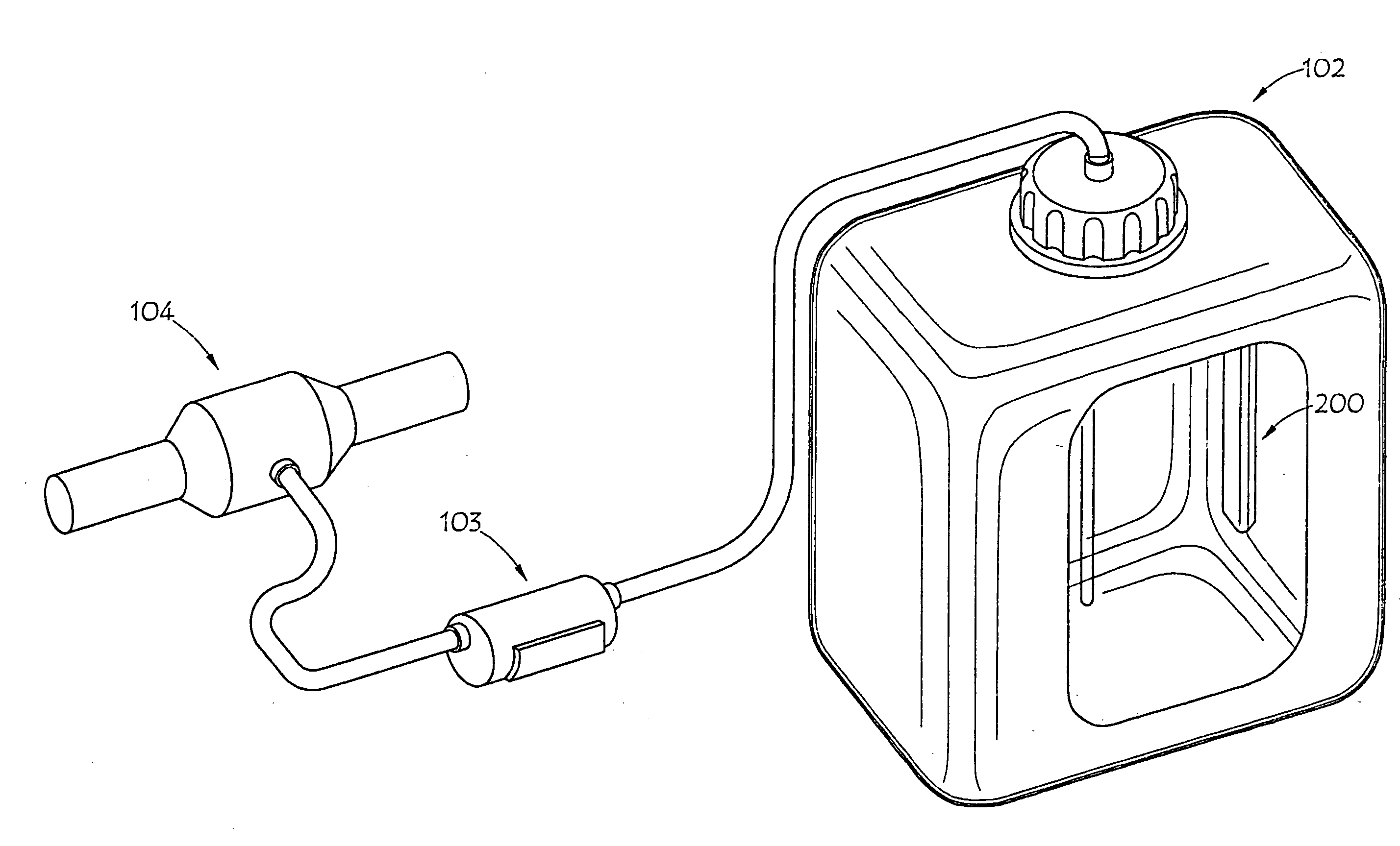
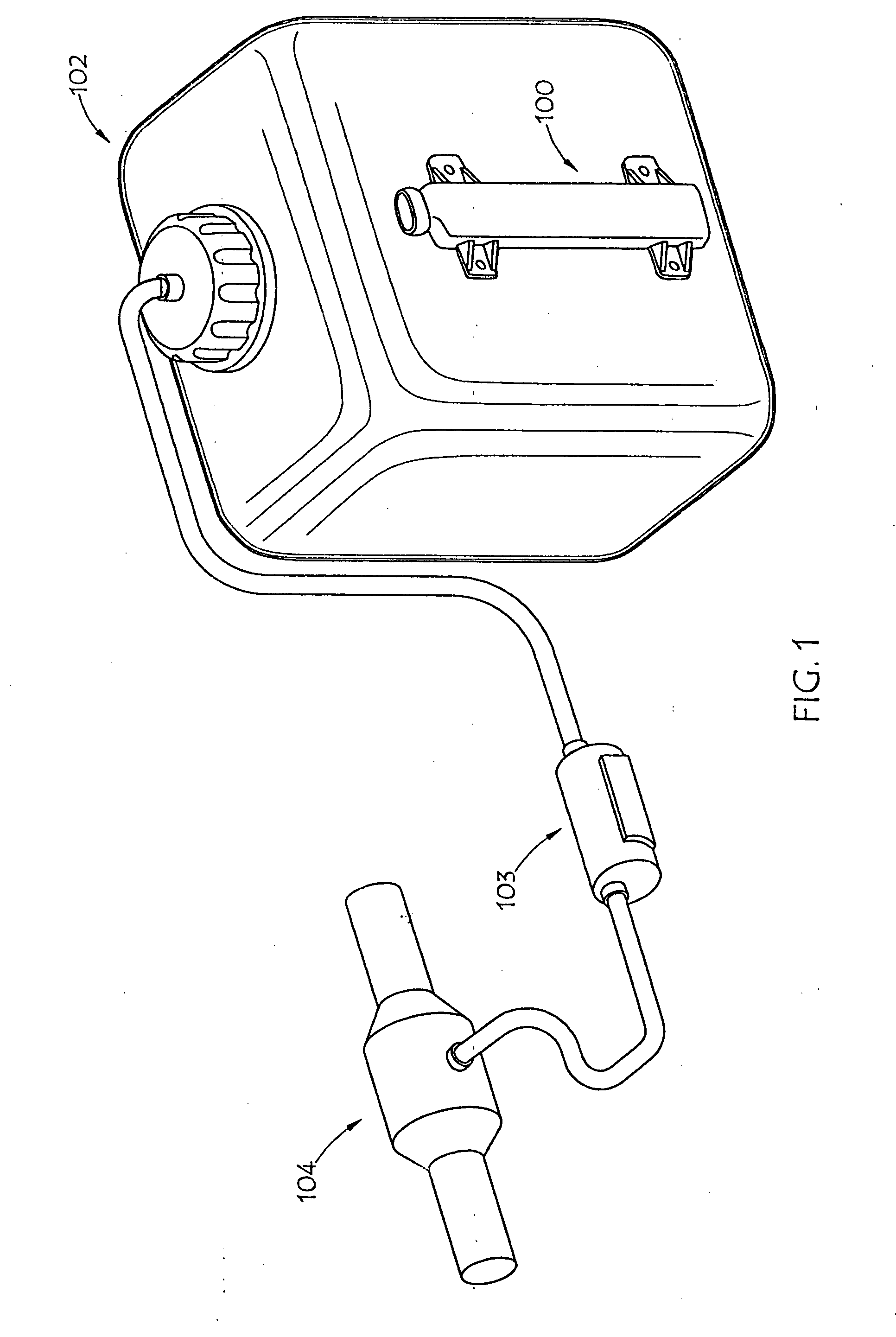
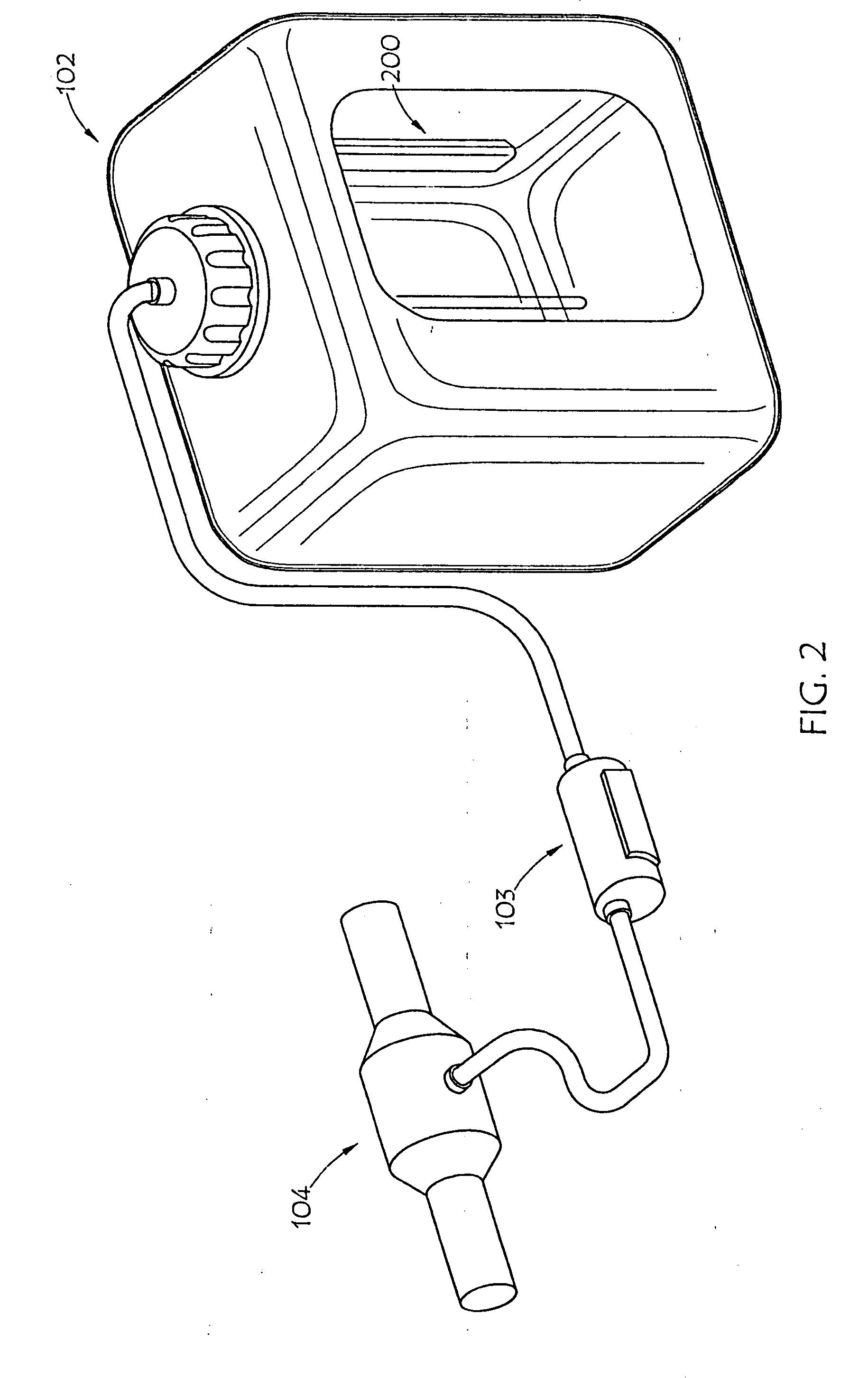
[0044]FIG. 1 shows an embodiment of AUS monitoring device 100 of the present invention disposed in conjunction with urea tank 102, such as mounting the AUS monitoring device to the exterior of the tank. Various embodiments call for mounting the AUS monitoring device of the present invention to the exterior side or bottom of a tank. Urea tank 102 may be made from a non-conductive material such as plastic. AUS from urea tank 102 ma...


PUM


Abstract

A liquid level, composition and contamination sensor generates an RF signal across a resonant circuit that includes a variable inductor and capacitor. The resulting electromagnetic radiation is propagated into the liquid and changes in impedance and resonance of the resonant circuit that result from changes in the conductivity and dielectric properties of the liquid, which are proportional to liquid content and volume, are detected. The conductivity and dielectric properties of the liquid are measured, based on the changed impedance and resonance of the resonant circuit, and are compared to determine aging and contamination of the urea solution by other liquids. Also, an optical sensor may be submerged in the liquid to determine the refractive index of the liquid. The refractive index of the liquid may be used to determine: if the liquid is water or a urea solution; the concentration of a urea solution.

Description

CROSS-REFERENCE TO RELATED APPLICATION[0001]This application claims the benefit of U.S. Provisional Patent Application Ser. No. 61 / 269,648, entitled Liquid Level, Composition and Contamination Sensing Apparatus, Systems and Methods Using EMF Wave Propagation, filed Jun. 26, 2009, which is incorporated herein by reference.BACKGROUND[0002]1. Field of the Invention[0003]This invention relates generally to systems and methods for sensing the condition of liquid in a tank or container. More particularly, embodiments of the present invention relate to sensing characteristics of automotive urea solution in a urea tank in a motor vehicle, the composition of fuel in a fuel tank, and / or the like, particularly liquid level, composition and contamination, by propagating electromagnetic waves into such a tank.[0004]2. Description of the Prior Art[0005]Selective Catalytic Reduction (SCR) vehicles, also referred to as Euro V vehicles, are diesel powered motor vehicles which are compatible with the...

Claims


Application Information

Patent Timeline
IPC IPC(8): G01R27/26
CPCF01N3/2066F01N2610/02G01F23/2922G01N27/02G01N33/2847G01N33/2852F01N2900/1818Y02T10/47F01N11/00F01N2550/05F01N2900/1811F01N2900/1814Y02T10/24G01N21/41G01N21/8507Y02T10/12Y02T10/40G01F23/26G01N27/22G01N33/22F01N3/20
Inventor MCCALL, ALAN KENNETHBOUDAOUD, IDIR
Owner SCHRADER ELECTRONICS LTD
Learn More