
Method for producing metal microparticles, and metal colloidal solution containing the metal microparticles

a technology of metal microparticles and colloidal solution, which is applied in the direction of electrolytic organic production, instruments, conductors, etc., can solve the problems of difficult temperature control, difficult to conduct a uniform reaction, and difficult concentration control, so as to achieve continuous and efficient production, high production efficiency, and the effect of increasing in siz

Active Publication Date: 2010-12-30
M TECHN
View PDF6 Cites 25 Cited by
  • Summary
  • Abstract
  • Description
  • Claims
  • Application Information

AI Technical Summary

Benefits of technology

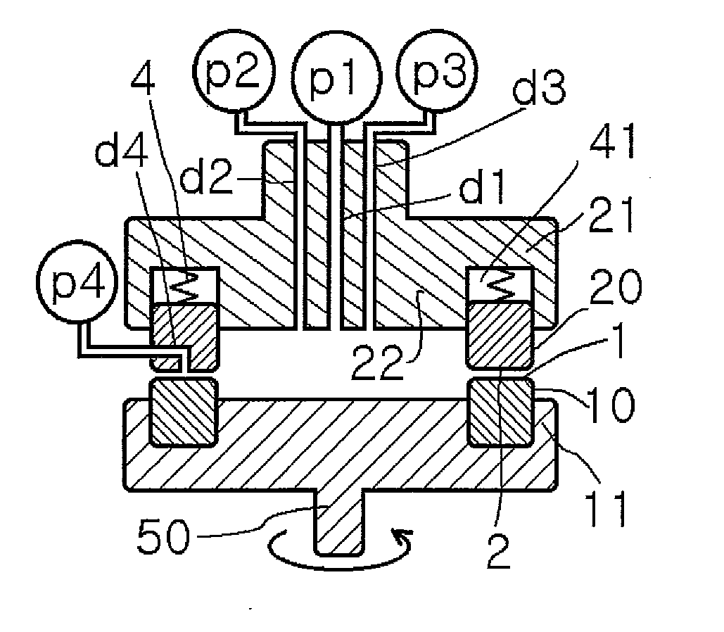
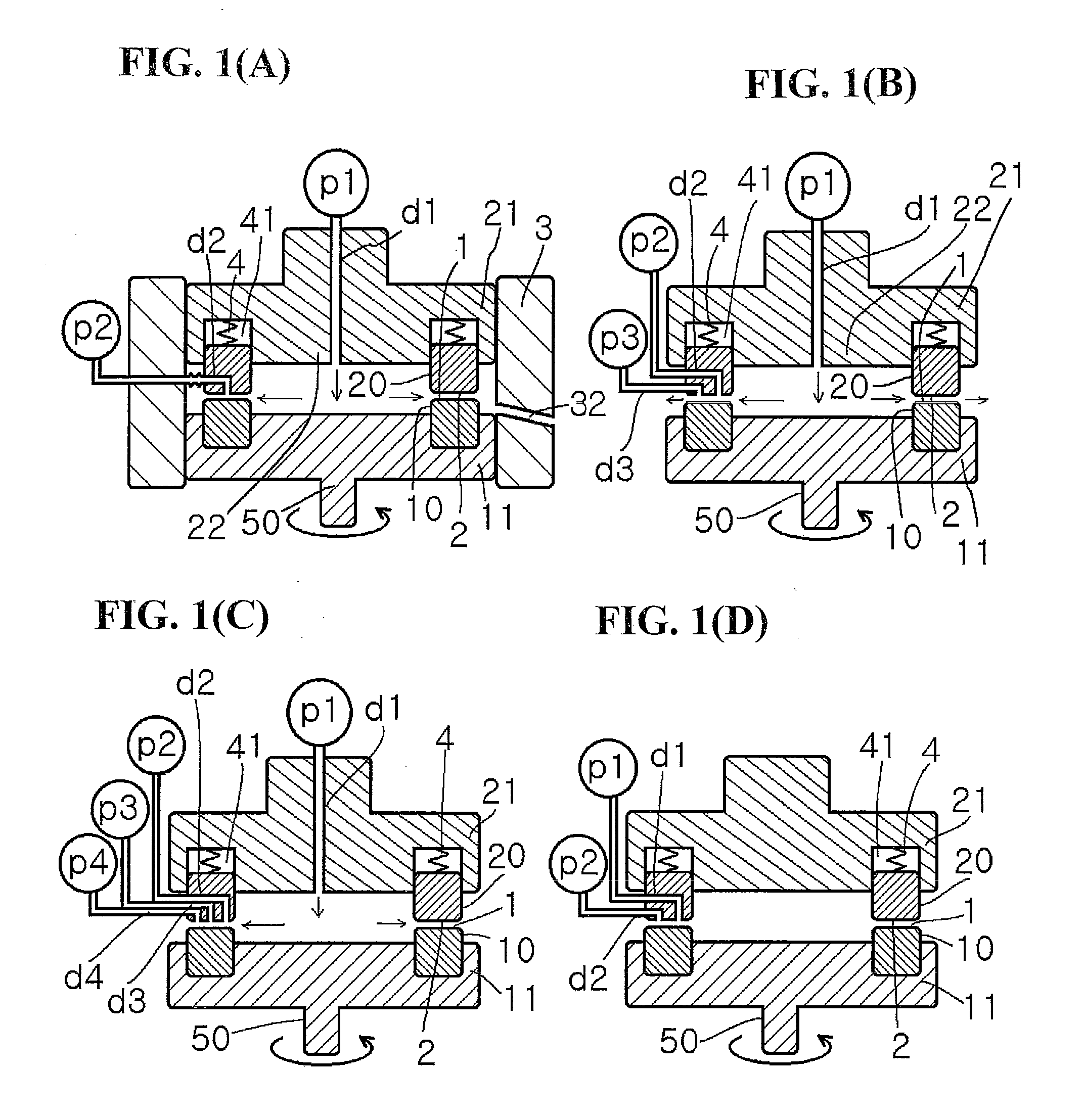
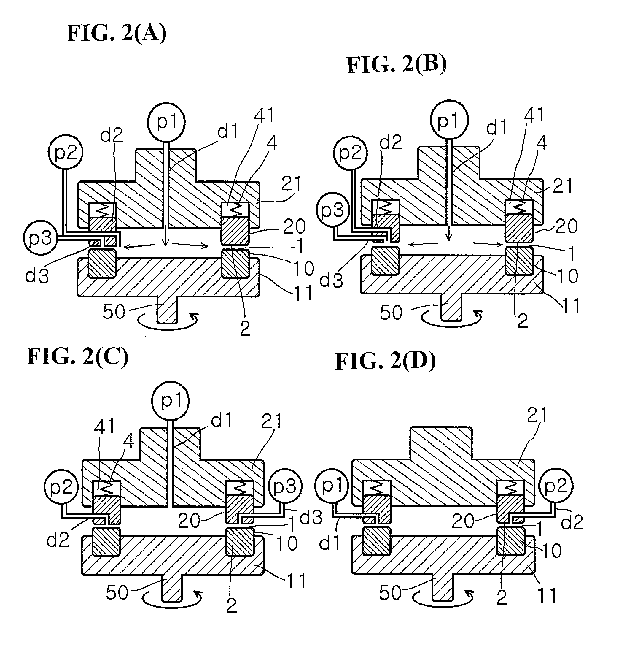
[0010]In view of the foregoing, the present invention provides a method for producing metal microparticles, wherein a metal compound is reduced in a thin film fluid formed between processing surfaces arranged to be opposite to each other so as to be able to approach to and separate from each other, at least one of which rotates relative to the other, thereby achieving a free change in the Reynolds number in its thin film, so that according to the object, a monodisperse metal colloidal solution can be prepared without clogging with products because of self-dischargeability, without necessity for high pressure and with high productivity to give metal microparticles excellent in re-dispersibility, and the problem described above was thereby solved.
[0019]The present invention relates to a method for producing metal microparticles, which comprises reducing a metal compound in a thin film fluid formed between processing surfaces arranged to be opposite to each other so as to be able to approach to and separate from each other, at least one of which rotates relative to the other, wherein a monodisperse metal colloidal solution having an average particle size smaller than that of metal microparticles obtained by a usual reaction method can be obtained. The present invention is a preferable method for producing metal microparticles, wherein metal microparticles can be obtained continuously and efficiently while coping with production with high production efficiency. Depending on a necessary amount of production, the apparatus can grow in size by using general scale-up concept.

Problems solved by technology

In the batch type method, however, it is generally difficult to control the temperature in the batch reaction apparatus and it is thus inevitably difficult to conduct a uniform reaction.
In addition, the concentration control is also difficult because complete uniform stirring is necessary.
Further, a long reaction time is also necessary, and thus it is extremely difficult to control all the reaction conditions.
Although there are many advantages in micro-devices and system when the general micro-reactor is used, there are actually many problems as follows: when the diameter of a micro-flow path is decreased, the pressure loss is inversely proportional to the fourth root of the flow path, that is, a fluid-sending pressure that is so high as to make it hard to obtain a pump for sending a fluid is necessary; in the case of a reaction involving separation, the phenomenon of clogging a flow path with products and the closure of a micro-flow path by foam generated by the reaction; the reaction is expected fundamentally by the diffusion speed of molecules, and thus the micro-spaces are not effective or applicable to every reaction, and in practice, successful ones should be selected by testing the reaction in a trial-and-error system.
Scaling up has been coped with a method of increasing the number of microreactors, that is numbering up, but the number of microreactors which can be stuck is limited to several dozen, thus inherently aiming exclusively at products of high value, and the increase in the number of devices leads to an increase the absolute number of failure causes, and when the problem of clogging actually occurs, it can be very difficult to detect a problem site such as failure site.

Method used


Image

  • Method for producing metal microparticles, and metal colloidal solution containing the metal microparticles
  • Method for producing metal microparticles, and metal colloidal solution containing the metal microparticles
  • Method for producing metal microparticles, and metal colloidal solution containing the metal microparticles

Examples


example 1

[0397]While 10% hydrazine aqueous solution was sent as a first fluid from the center at a supply pressure / back pressure of 0.02 MPa / 0.01 MPa, at a revolution number of 1000 rpm and at a sending solution temperature of 80° C., an aqueous solution of 20% silver nitrate / 2% polyvinyl pyrrolidone (molecular weight 20000), just after adjusted to pH 12 with ammonia water, was introduced at a rate of 10 ml / min. as a second fluid into the space between the processing surfaces 1 and 2. An aqueous colloidal silver solution having yellow plasmon absorption was discharged from the processing surfaces 1 and 2. A further discharged solution even when stored in a glass container did not show a silver mirror reaction without forming a film of silver on the wall surface of the container.

[0398]Then, the operation of centrifuging the obtained colloidal silver solution to remove impurities lighter than silver microparticles was repeatedly conducted, then the silver microparticles were washed with purifi...

example 2

[0399]While 10% hydrazine aqueous solution was sent as a first fluid from the center at a supply pressure / back pressure of 0.10 MPa / 0.01 MPa, at a revolution number of 2000 rpm and at a sending solution temperature of 80° C., an aqueous solution of 20% silver nitrate / 2% polyvinyl pyrrolidone (molecular weight 20000), just after adjusted to pH 12 with ammonia water, was introduced at a rate of 10 ml / min. as a second fluid into the space between the processing surfaces 1 and 2. An aqueous colloidal silver solution having yellow plasmon absorption was discharged from the processing surfaces 1 and 2. A further discharged solution even when stored in a glass container did not show a silver mirror reaction without forming a film of silver on the wall surface of the container.

[0400]Then, the operation of centrifuging the obtained colloidal silver solution to remove impurities lighter than silver microparticles was repeatedly conducted, then the silver microparticles were washed with purifi...

example 3

[0401]While 10% dimethylaminoethanol (DMAE) aqueous solution was sent as a first fluid from the center at a supply pressure / back pressure of 0.02 MPa / 0.02 MPa, at a revolution number of 1000 rpm and at a sending solution temperature of 80° C., an aqueous solution of 20% silver nitrate / 2% BYK-190 (manufactured by BYK-Chemie), just after adjusted to pH 12 with ammonia water, was introduced at a rate of 10 ml / min. as a second fluid into the space between the processing surfaces 1 and 2. An aqueous colloidal silver solution having yellow plasmon absorption was discharged from the processing surfaces 1 and 2. A further discharged solution even when stored in a glass container did not show a silver mirror reaction without forming a film of silver on the wall surface of the container.

[0402]Then, the operation of centrifuging the obtained colloidal silver solution to remove impurities lighter than silver microparticles was repeatedly conducted, then the silver microparticles were washed wit...


PUM

PropertyMeasurementUnit
Fractionaaaaaaaaaa
Fractionaaaaaaaaaa
Fractionaaaaaaaaaa

Abstract

An aqueous solution containing a polymer dispersant and a metal compound, and an aqueous solution of a reducing agent, are joined together and uniformly mixed while being subjected to reduction reaction to give metal microparticles, in a thin film fluid formed between processing surfaces arranged to be opposite to each other so as to be able to approach to and separate from each other, at least one of which rotates relative to the other, by using a reaction apparatus of uniform stirring and mixing the above aqueous solutions.

Description

TECHNICAL FIELD[0001]The present invention relates to metal microparticles and a method for producing a metal colloidal solution produced therefrom.BACKGROUND ART[0002]Patent Document 1: JP-A H11-080647[0003]Patent Document 2: JP-A 2000-239853[0004]Patent Document 3: JP-A 2006-321948[0005]Patent Document 4: JP-A 2004-33901[0006]Generally, metal nanoparticles have a very high ratio of the particle surface thereof to the total number of atoms and have physical properties different from those of bulk metal. Particularly, metal nanoparticles having a diameter of 10 nm or less exhibit a high catalyst function and undergo a reduction in melting point, and in the case of gold, silver, copper, or the like show a physical property of having absorption at a specific wavelength, called plasmon absorption in the visible light range.[0007]A solution having such metal microparticles dispersed uniformly therein, that is, a metal colloidal solution, has been utilized in various fields by making use...

Claims


Application Information

Patent Timeline
IPC IPC(8): H01B1/22C04B14/00C25C3/00B22F9/18
CPCB22F9/24B01J13/0043
Inventor ENOMURA, MASAKAZU
Owner M TECHN
Learn More