
Output-level-controlling converter device

a converter device and output level technology, applied in the direction of gain control, transducer casing/cabinet/support, electrical transducer, etc., can solve the problems of high signal distortion, unexpected and exceedingly high voltage of audio frequency power amplifiers, and excessively large signal output power, so as to reduce the distortion of saturation output signal, reduce the voltage gain of reference signal, and reduce the output power

Inactive Publication Date: 2010-09-30
TAI 1 MICROELECTRONICS CORP
View PDF3 Cites 7 Cited by
  • Summary
  • Abstract
  • Description
  • Claims
  • Application Information

AI Technical Summary

Benefits of technology

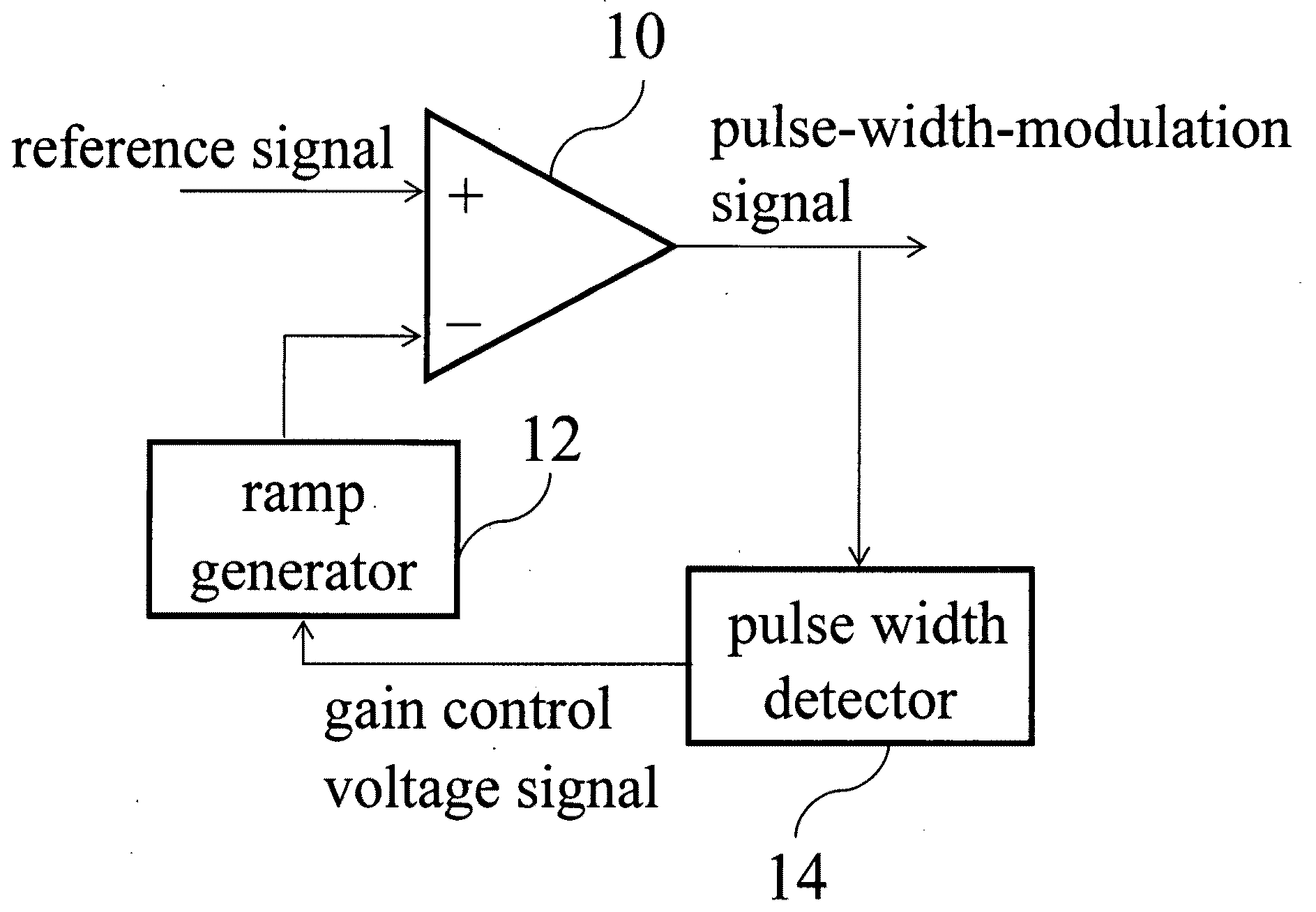
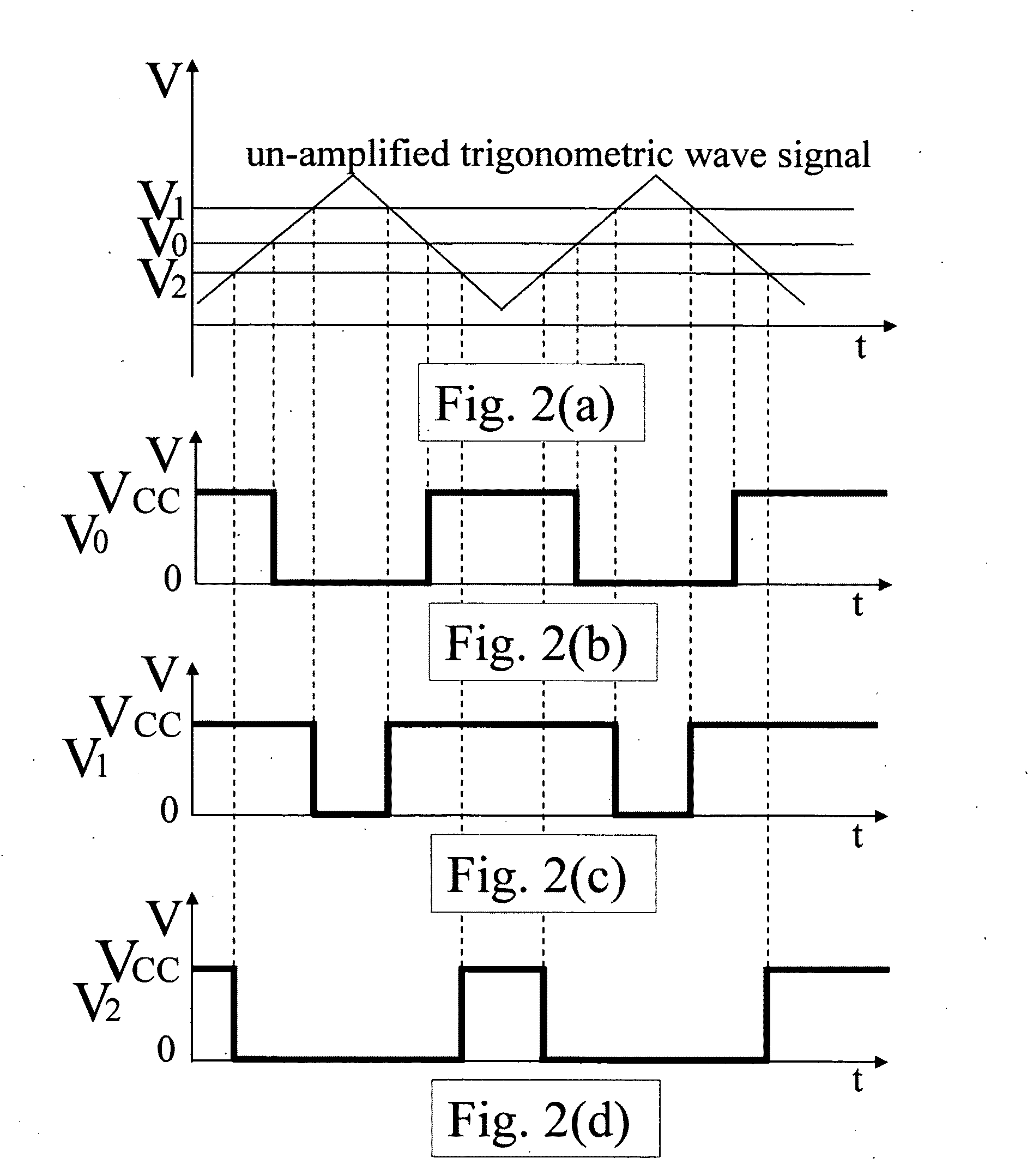
[0008]A major objective of the present invention is to provide an output-level-controlling converter device, wherein, an analog-to-PWM converter is utilized to receive a ramp signal and a reference signal, and perform analog-to-PWM conversion for the reference signal, and output a pulse-width-modulation (PWM) signal, and when duty cycle of this modulation signal is close to 0% or 100%, that is used to increase the amplitude of voltage of a ramp signal, so as to make the current duty cycle greater or less than the original duty cycle. In addition, when voltage of a ramp signal is cut off by a voltage upper limit or a voltage lower limit, this analog-to-PWM converter is used to perform attenuation of the reference signal digitally, hereby reducing voltage gain of the reference signal. The application of this output-level-controlling converter device will enable an ordinary audio frequency power amplifier to reduce the distortion of a saturation output signal or reduce its output power for protecting loudspeaker while proceeding with signal conversions digitally.
[0009]In order to achieve the above-mentioned objective, the present invention provides an output-level-controlling converter device, including a ramp generator, used to generate a ramp signal; and an analog-to-PWM converter, with its first and second terminals utilized to receive the ramp signal and a reference signal, and perform analog-to-PWM conversion for the reference signal, hereby outputting a pulse-width-modulation signal. Each of the output terminals of the ramp generator and the analog-to-PWM converter is connected respectively to a pulse width detector, and that is used to detect the duty cycle of a pulse-width-modulation signal, and output a gain control voltage signal based on said duty cycle. Then, when the duty cycle is close to 0% or 100%, the ramp generator is used to increase the voltage amplitude of said ramp signal based on voltage value of the gain control voltage signal, thus making the duty cycle of the pulse-width-modulation signal greater than or less than the original duty cycle, hereby reducing the voltage gain of the reference signal.

Problems solved by technology

Due to the fact that the dynamic range of music or audio frequency signal variations is rather large, and its sound intensity will vary significantly along with the time, and since the magnitudes of the audio frequency signals transmitted to an audio frequency power amplifier from various broadcasting devices vary greatly, thus on certain occasions, the audio frequency power amplifier will receive signals of unexpectedly and exceedingly high voltage.
And when this audio frequency power amplifier receives an input signal of exceedingly high voltage, the correspondingly high voltage of its output signal will be cut off by the upper and lower limits of power source voltage, thus resulting in high distortion of signals.
In this situation, harmonic distortion will be exceedingly large, hereby causing loudspeaker to produce very loud but unpleasant sound, or even burning out the loudspeaker.
In the above-mentioned conditions, in case that an audio frequency power amplifier is used to drive a base or super base loudspeaker, then the output sound of loudspeaker is very much unpleasant.
Or, otherwise, in case that an audio frequency power amplifier is used to drive a loudspeaker of small sound volume capacity, such as, a loudspeaker of exceedingly small sound volume capacity in a portable electronic device, then this kind of loudspeaker is liable to be burned out.
However, this automatic gain controller (AGC) tends to increase / reduce voltage gain of amplifier in its normal operating range all the time.
As such, the output voltage of an amplifier is not capable of reproducing and broadcasting the low sound and loud sound of the music according to their original proportion in its entire fidelity, hereby resulting in reduction in the dynamic voltage range of output signal variations.
Therefore, presently, the performance of this kind of design is not quite satisfactory.

Method used


Image

  • Output-level-controlling converter device
  • Output-level-controlling converter device
  • Output-level-controlling converter device

Examples


Embodiment Construction

[0018]The purpose, construction, features, functions and advantages of the present invention can be appreciated and understood more thoroughly through the following detailed descriptions with reference to the attached drawings.

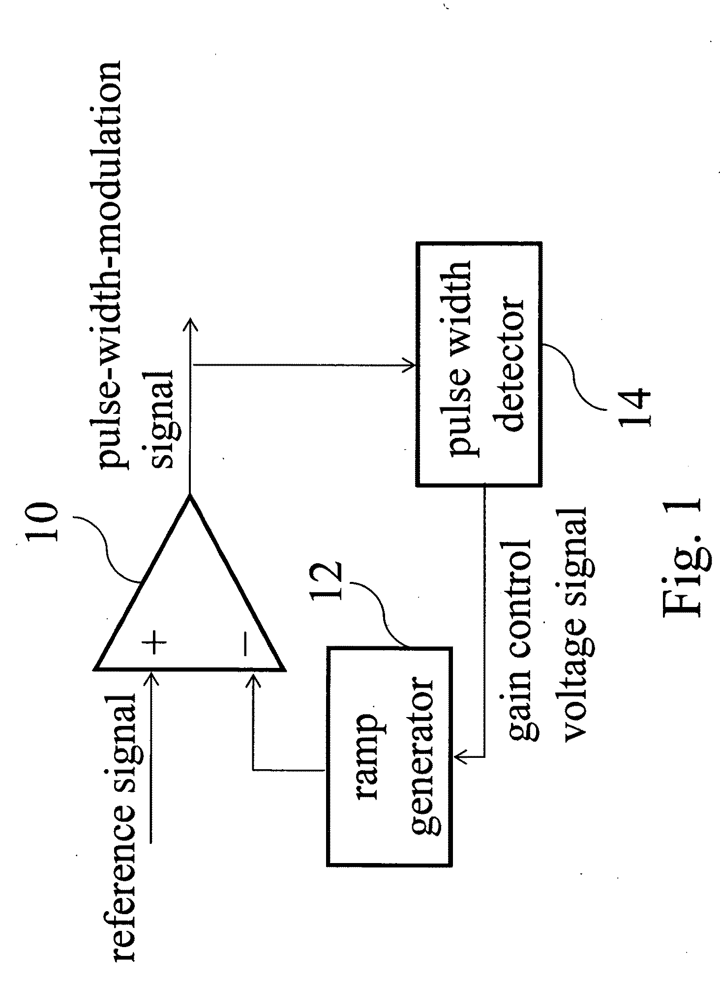
[0019]In order to eliminate or at least alleviate the phenomenon that an audio frequency power amplifier tends to produce serious signal distortion when receiving an input signal of exceedingly high voltage, the present invention discloses an output-level-controlling converter device, that can be utilized in performing signal conversion digitally for an ordinary audio frequency power amplifier. Referring to FIG. 1 for a schematic diagram of an output-level-controlling converter device according to a first embodiment of the present invention. As shown in FIG. 1, the output-level-controlling converter device of the present invention includes an analog-to-PWM converter 10, having its negative input terminal connected to a ramp generator 12, and that is used to ge...


PUM


Abstract

An output-level-controlling converter device, including a ramp generator, used to generate a ramp signal; and an analog-to-PWM converter, said converter is used to perform conversion digitally for a reference signal by making use of said ramp signal, and output a pulse-width-modulation signal; and a pulse width detector, used to detect a duty cycle of said pulse-width-modulation signal, and output a gain control voltage signal based on said duty cycle, and when said duty cycle is close to 0% or 100%, said ramp generator is used to increase a voltage amplitude of said ramp signal based on a voltage value of said gain control voltage signal, hereby increasing or decreasing said duty cycle of said pulse-width-modulation signal for reducing voltage gain of said reference signal.

Description

BACKGROUND OF THE INVENTION[0001]1. Field of the Invention[0002]The present invention relates to a converter device, and in particular to an output-level-controlling converter device.[0003]2. The Prior Arts[0004]In general, the design and operation principle of an amplifier is that, the amplifier is utilized to receive an input signal, then amplify the signal, and finally output the amplified signal. In this way, the design and operation principle of an ordinary audio frequency power amplifier is to receive an audio frequency signal, amplify the signal, and finally output a signal of large current into a loudspeaker. Due to the fact that the dynamic range of music or audio frequency signal variations is rather large, and its sound intensity will vary significantly along with the time, and since the magnitudes of the audio frequency signals transmitted to an audio frequency power amplifier from various broadcasting devices vary greatly, thus on certain occasions, the audio frequency ...

Claims


Application Information

Patent Timeline
Patent Type & Authority Applications(United States)
IPC IPC(8): H04B15/00
CPCH03G3/3005H03F3/217
Inventor TAI, JY-DER DAVID
Owner TAI 1 MICROELECTRONICS CORP
Learn More