Patterning of ionic polymers
a technology of ionic polymers and polymers, applied in the field of patterning polymers, can solve the problems of inherently non-parallelel, slow, and limited conventional and more specialized photolithography techniques for patterning polymers, and achieve the effects of improving the accuracy of the patterning polymer, and improving the patterning
- Summary
- Abstract
- Description
- Claims
- Application Information
AI Technical Summary
Benefits of technology
Problems solved by technology
Method used
Image


Examples
example 1
Patterning PAA within Microfluidic Channels Using Metal Cation Solutions
[0098]This example shows that ionotropic polymers (e.g., PAA) can be patterned using microfluidic channels and metal cation solutions as crosslinkers according to one embodiment of the invention.
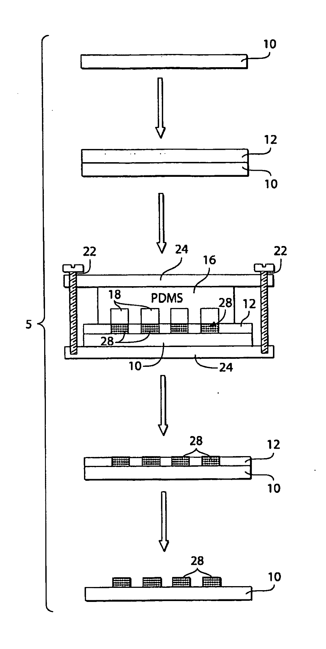
[0099]The following procedure was used to pattern PAA with microfluidic channels using metal cation solutions. A 3.5% (w / v) aqueous solution (pH 2.5) of PAA (Mw ˜50,000) was spin-coated (1500 rpm for 15 seconds) onto either a silicon wafer or a glass slide pre-treated with oxygen plasma using a plasma cleaner (˜266 Pa, 100 W, Harrick Scientific Model PDC-32G) for 1 minute. The film was then heated for 15 minutes at 150° C. on a hot plate. A second layer of 3.5% PAA sodium salt (pH 7.2) was spun (1500 rpm for 15 seconds) onto the first layer of PAA, and heated for 2 minutes at 150° C. The first layer of PAA (pH 2.5) increased the strength of adhesion of the PAA film to the substrate. The total thickness of the PAA film wa...
example 2
Formation and Characterization of Pd, PbS, and ZnS Nanoparticles in the PAA Matrix
[0105]This example shows that the PAA features produced in Example 1 can be used as templates for nanoparticle growth according to one embodiment of the invention.
[0106]The reduction of Pd(II) into metallic colloids (Pd(0)) is one especially practical example of the chemistry that can be done with the patterned, crosslinking metal ions: Pd(0) can reduce precious metal cations such as Au(III), and provides a catalytic surface for other chemical reactions (e.g., the reduction of Cu(II)). Both of these applications are now described.
[0107]Two different reducing agents were used to convert the Pd(II) embedded in the PAA matrix to Pd(0) nanoparticles: methanol, a mild reductant, and a 0.1 M aqueous solution of BDC (in the presence of 1M CaCl2, a replacement cation), a stronger reductant than methanol. Reduction of the CCL-PAA / Pd(II) by BDC without the replacement cation in solution resulted in dissolution o...
example 3
Chemical Reactions with Patterned Pd(0) Nanoparticles
[0110]This example shows that patterned ionotropic polymers can be used for associating a chemical and / or biological component.
[0111]Reduction of [NaAuCl4] to Au(0) Nanoparticles. After reduction of the Pd(II) to Pd(0) using either methanol or BDC, the PAA film containing Pd(0) colloids was exposed to a solution of 0.5 M NaAuCl4 for 30 minutes. During reduction of gold, the PAA film acquired a red color when MeOH was used as the reductant, or a blue color when BDC was used as the reductant; the red color indicated the presence of gold colloids, and the blue color indicated the presence of their aggregates. XPS and UV-Vis absorption measurements (see FIGS. 6 and 9, respectively) confirmed these assignments. The color of the Au particles was determined by the method by which the Pd(II) was reduced. The use of MeOH may have yielded mainly individual Au nanoparticles because it is, a weak reducer of Pd(II). Reduction with MeOH produce...
PUM
| Property | Measurement | Unit |
|---|---|---|
| Length | aaaaa | aaaaa |
| Length | aaaaa | aaaaa |
| Length | aaaaa | aaaaa |
Abstract
Description
Claims
Application Information
 - R&D
- Intellectual Property
- Life Sciences
- Materials
- Tech Scout
- Unparalleled Data Quality
- Higher Quality Content
- 60% Fewer Hallucinations
Browse by: Latest US Patents, China's latest patents, Technical Efficacy Thesaurus, Application Domain, Technology Topic, Popular Technical Reports.
© 2025 PatSnap. All rights reserved.Legal|Privacy policy|Modern Slavery Act Transparency Statement|Sitemap|About US| Contact US: help@patsnap.com