
Microfluidic fuel cell systems with embedded materials and structures and method thereof

Inactive Publication Date: 2005-07-26
LAWRENCE LIVERMORE NAT SECURITY LLC
View PDF11 Cites 47 Cited by
  • Summary
  • Abstract
  • Description
  • Claims
  • Application Information

AI Technical Summary

Benefits of technology

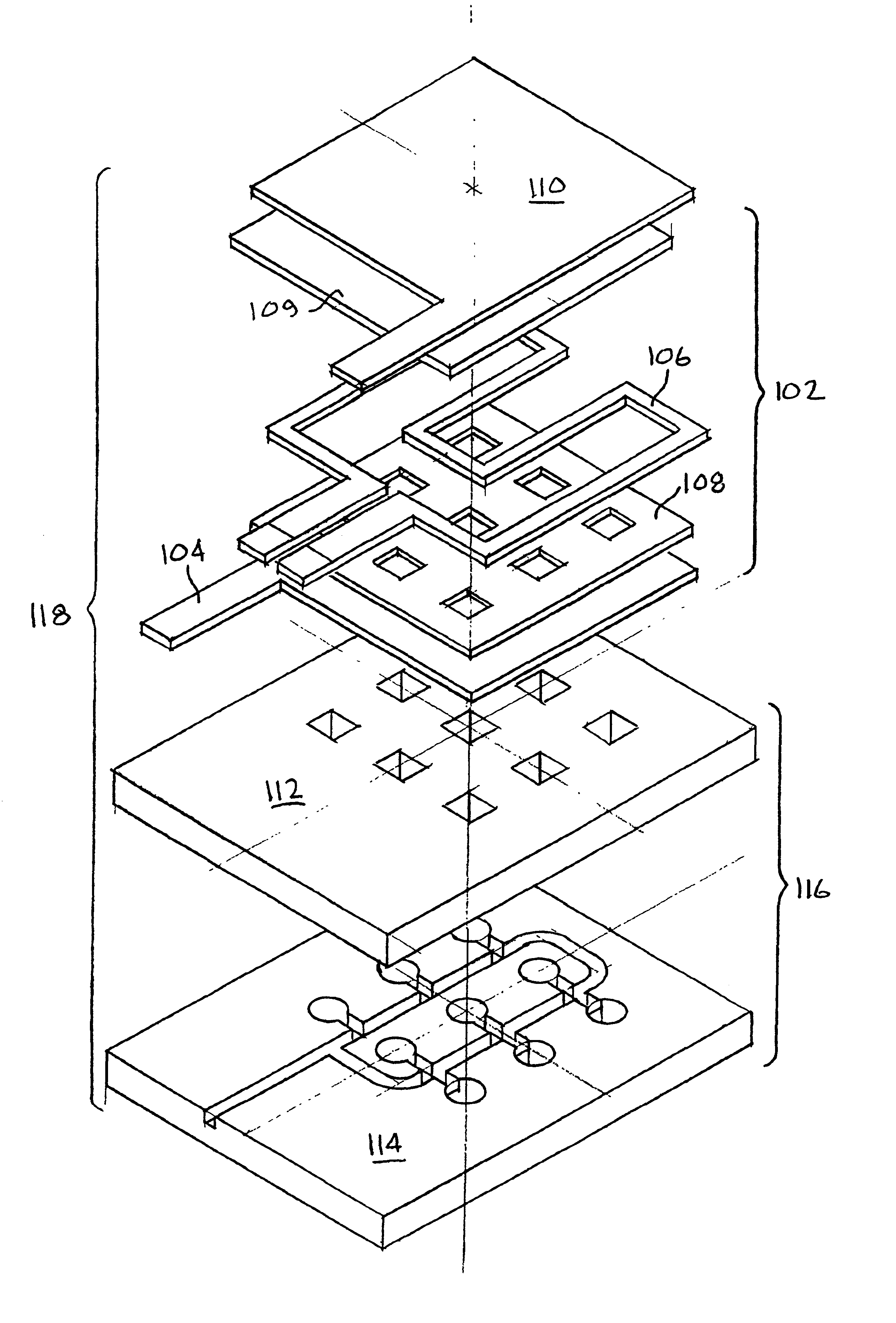
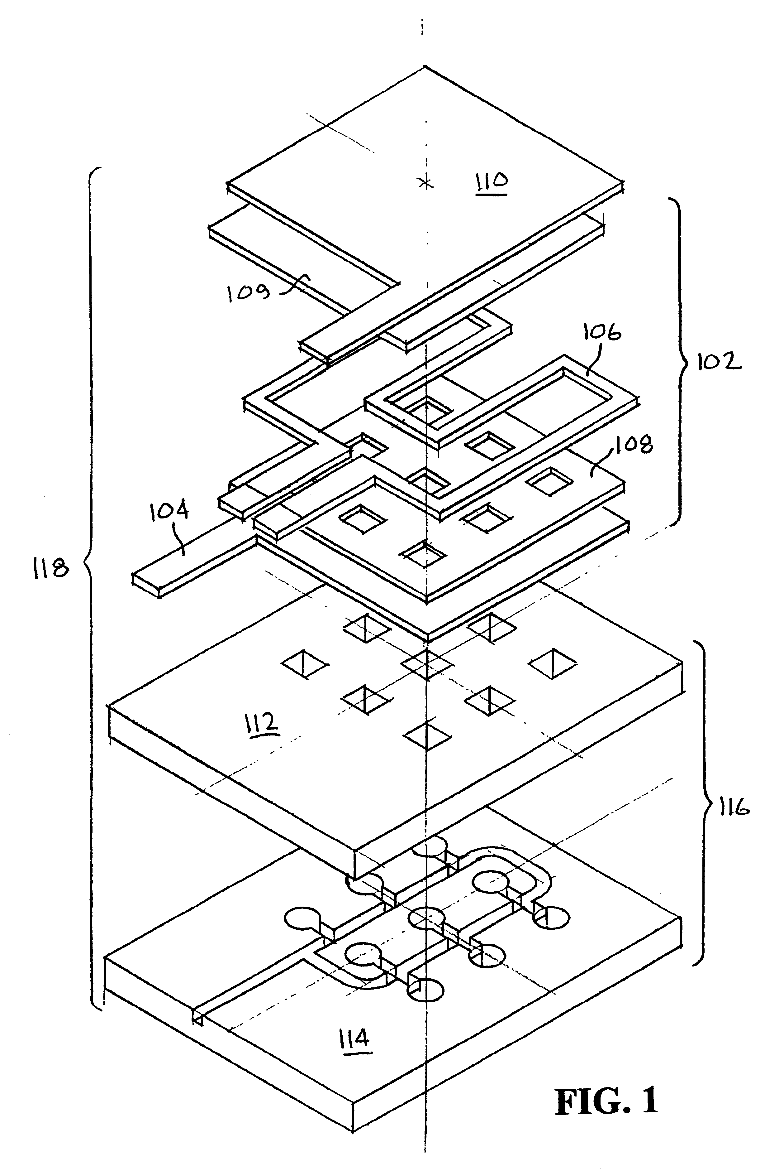
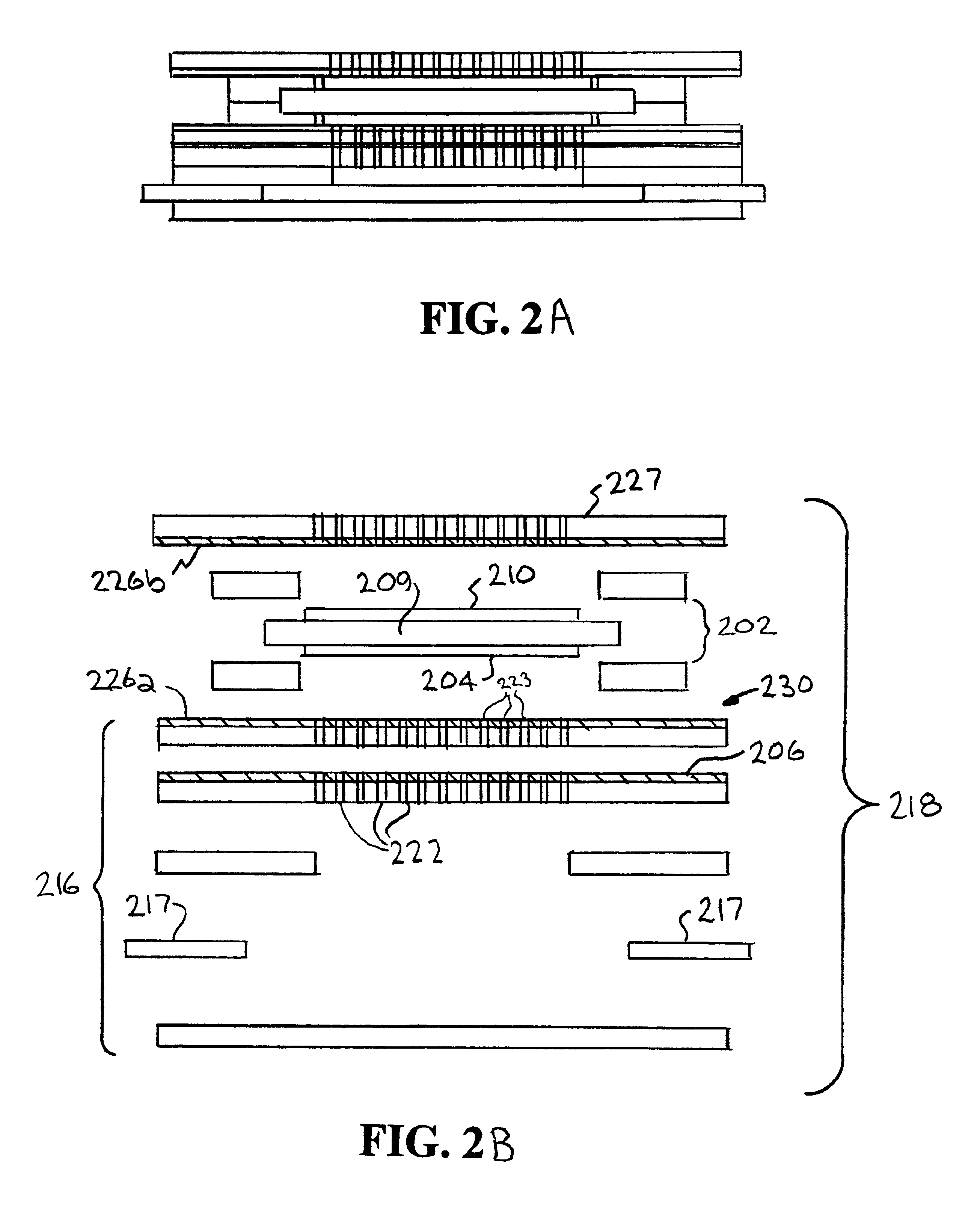
[0006]Another aspect of the invention includes a microfluidic fuel cell system comprising: at least one fuel cell having an MEA containing an anode, anode catalyst, an electrolyte, cathode catalyst, and a cathode, the electrolyte comprising a proton exchange membrane having a thickness in the range of about 5-50 μm and operating at a temperature less than or equal to about 200° C.; a microfluidic fuel distribution structure comprising at least one microfluidic channel connecting a reservoir containing

Problems solved by technology

Since polluting waste gases are not emitted, the attendant processes and equipment required to neutralize these harmful by-products are unnecessary.

Method used


Image

  • Microfluidic fuel cell systems with embedded materials and structures and method thereof
  • Microfluidic fuel cell systems with embedded materials and structures and method thereof
  • Microfluidic fuel cell systems with embedded materials and structures and method thereof

Examples


example 1

[0030]Pre-cured PDMS is poured onto a silicon mold with the desired design etched into it, e.g., a honeycomb array 50 microns across and 50 microns high, and degassed by placing in a vacuum. The degassing ensures that air bubbles are not trapped between the PDMS and the silicon mold. The PDMS is then cured for about 4 hours at about 75° C. The mold and the attached PDMS can then be placed into about a <50% potassium hydroxide (KOH) bath to remove the silicon. The PDMS remaining will retain the pattern of the silicon.

example 2

[0031]An array of about 100,000 small diameter posts, i.e., <10 μm, are formed on a silicon substrate by plasma etching to a height in the range of about 20 μm to about 50 μm. The silicon is then coated with gold to act as an anti-stick layer. The PDMS is then poured over the posts and cured for about 4 hours at about 75° C. The PDMS is made thin enough so the tops of the silicon posts are exposed, i.e., <20-50 μm. After curing, the PDMS is pulled off the mold, creating a porous support structure for the fuel cell anode.


PUM

PropertyMeasurementUnit
Temperatureaaaaaaaaaa
Poweraaaaaaaaaa
Diameteraaaaaaaaaa

Abstract

Described herein is a process for fabricating microfluidic systems with embedded components in which micron-scale features are molded into the polymeric material polydimethylsiloxane (PDMS). Micromachining is used to create a mold master and the liquid precursors for PDMS are poured over the mold and allowed to cure. The PDMS is then removed form the mold and bonded to another material such as PDMS, glass, or silicon after a simple surface preparation step to form sealed microchannels.

Description

[0001]The United States Government has rights in this invention pursuant to Contract No. W-7405-ENG-48 between the United States Department of Energy and the University of California for the operation of Lawrence Livermore National Laboratory.BACKGROUND[0002]This invention relates to fuel cells. Work is commonly derived from fuel by a combustion process which uses the pressure of expanding gases to turn a turbine or move a reciprocating piston and, ultimately, provide torque to a driveshaft. This torque is then usually used for propulsion or to generate electrical power. In the latter case, the electrical power is often times reconverted into mechanical work.[0003]The by-products of the combustion process are waste gases, which contaminate the atmosphere or, if pollution is to be avoided or at least reduced, reacted with catalysts to produce benign compounds. The foregoing process is usually expensive and typically calls for operations and equipment that require extensive monitoring...

Claims


Application Information

Patent Timeline
IPC IPC(8): H01M8/02H01M4/86H01M8/04H01M8/10H01M8/00B01D65/00B01D67/00B01D71/70
CPCB01D65/003B01D67/0034B01D71/70H01M8/0239H01M8/04037H01M8/04089H01M8/1002H01M8/1097B01D67/0032Y10T29/49114H01M8/0245Y02E60/521B01D2323/24B01D2325/028B01D2325/08H01M8/1007Y02E60/50B01D71/701
Inventor MORSE, JEFFREY D.ROSE, KLINT AMAGHRIBI, MARIAMBENETT, WILLIAMKRULEVITCH, PETERHAMILTON, JULIEGRAFF, ROBERT T.JANKOWSKI, ALAN
Owner LAWRENCE LIVERMORE NAT SECURITY LLC
Learn More