
Thermodynamic power generation system

Inactive Publication Date: 2010-08-26
AMERICAN THERMAL POWER
View PDF49 Cites 23 Cited by
  • Summary
  • Abstract
  • Description
  • Claims
  • Application Information

AI Technical Summary

Benefits of technology

[0029]A rotating shaft is able to perform work, and this is accomplished by coupling the shaft to an electrical generating device thereby producing electrical power. Very large volumes of useful, moderate pressure gas are produced easily in this invention, at low temperatures, by using a working fluid such as a refrigerant. For instance, refrigerant R134 is one possible type of working fluid. Many other standard refrigerant types are also suitable. This refrigerant, in its liquid form, will boil very readily at low temperatures and pressures, and produce voluminous amounts of hot gas after being heated. R134 gas is particularly suited for this purpose, and completely avoids the need for high pressures and temperatures.
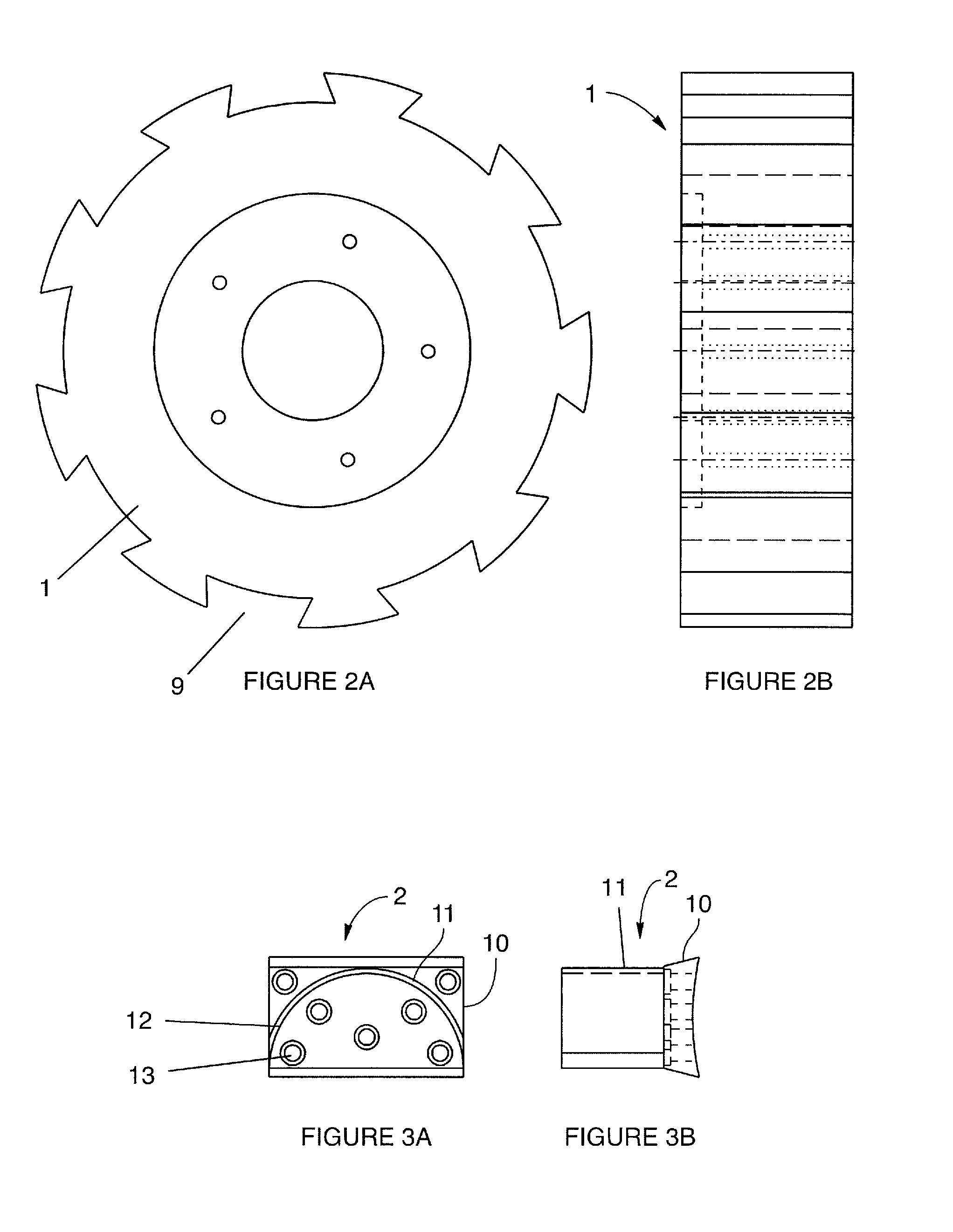
[0030]The blades mounted on the rotating member of the instant invention are not of traditional design. Prior art blades tend to be made for either high pressure and temperature gas flows—like in a jet engine for instance—or for flows of liquids, especially water, as in a hydroelectric plant for instance. These blades do not function well for low pressure and temperature gasses. The instant invention overcomes the limits of the prior art by combining a unique blade design with a particular design, to thereby extract power effectively under the desired conditions.
[0033]The force generated by the velocity of the gas flow is a vector quantity, and so a change in direction can be as effective as a change in speed. So, rather than have the flow crash to rest up against the blade surface, the blade surface is curved, and in turn the flow is also turned almost 180 degrees. This produces a momentum change almost double that than if the flow had been brought to rest against the blade. The combination of very high (even supersonic) velocities and radical change in direction result in a very large change in momentum. Thus a large reaction force is exerted on the blade.
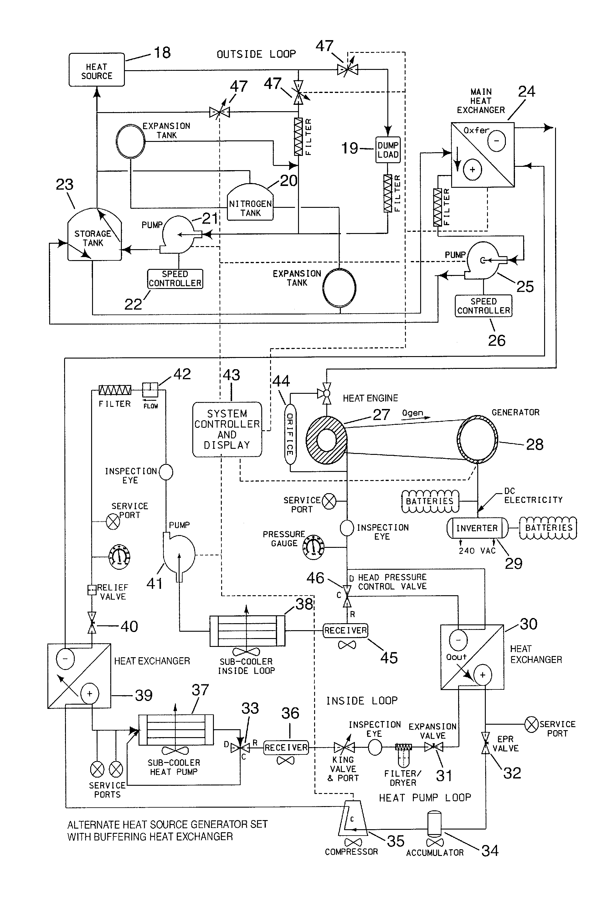
[0035]Additionally, to extract even greater performance from the whole system energy is recovered on both the input and exhaust of the turbine loop of the power system. On the input side of the engine, heat is brought from the external source to the heat exchanger serving the turbine loop. This is done by circulating a heat transfer fluid from the heat source over to the heat exchanger. Obviously not all of the available heat in the stream of heat transfer fluid will be absorbed into the engine in a single pass through. If the fluid were discarded at that point, the heat not absorbed would be lost. The system employs a pump and a loop to recirculate the fluid back to the source, and thence back around to the engine. In this way the heat is not wasted, and is presented again and again to the engine and is ultimately nearly all used. Even the energy required to operate the pump is imparted to the flow, and thus captured and circulated around the process for eventual use.
[0036]On the exhaust side of the turbine loop, a similar process is employed. The heat not converted in the engine to electricity is gathered up in a heat exchanger, and passed over into a recovery loop. This recovery loop is essentially a heat pump, and is used to raise the temperature of the working fluid back up, and it is then presented to another heat exchanger. This heat exchanger in turn is used to inject the heat back into the primary loop of the engine, at an appropriate point. Even the energy used to run the compressor in the heat pump is captured in the working fluid, and is injected into the engine for use. The combination of recovery of heat, and reuse of heat, on both the input and the exhaust sides of the engine is extremely effective and makes far more power output available than would otherwise be the case, with a given heat source.
[0039]It is yet another objective of the instant invention that is capable of efficiently utilizing low temperature heat sources and low pressure working fluids to generate substantial energy.

Problems solved by technology

These blades do not function well for low pressure and temperature gasses.

Method used


Image

  • Thermodynamic power generation system
  • Thermodynamic power generation system
  • Thermodynamic power generation system

Examples


Embodiment Construction

[0063]FIGS. 1 through 11 describe the heat engine. FIGS. 12 through 15 describe the complete thermodynamic system.

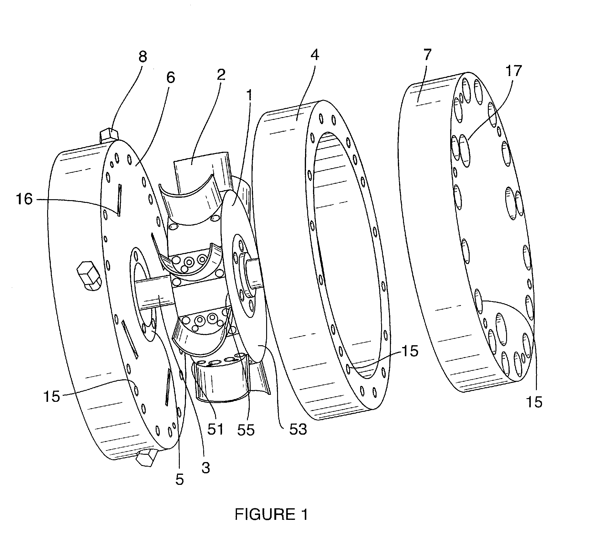
[0064]Beginning with the heat engine, FIG. 1 shows an exploded view of the heat engine components. As shown, the heat engine includes a left end bell 6, a right end bell 7, and a ring 4 that act together to enclose, seal, and support the engine. A rotating member 1 is mounted on a shaft 3, and the shaft 3 is supported by bearings 5 that are mounted in both left end bell 6 and right end bell 7. The shaft 3 is operatively connected to an electrical generator or other mechanical device to extract work from the rotating member 1. The left end housing includes inlet ports 16 each supporting a nozzle 8. The right hand bell 7 includes exhaust ports 17. While the invention is illustrated with four inlet nozzles, the number of inlet ports and corresponding nozzles can vary from one to many. The left end bell 6, the ring 4 and right end bell 7 are securely fastened together in a f...


PUM


Abstract

A power generation system that includes a heat source loop that supplies heat to a turbine loop. The heat can be waste heat from a steam turbine, industrial process or refrigeration or air-conditioning system, solar heat collectors or geothermal sources. The heat source loop may also include a heat storage medium to allow continuous operation even when the source of heat is intermittent. In the turbine loop a working fluid is boiled, injected into the turbine, recovered condensed and recycled. The power generation system further includes a heat reclaiming loop having a fluid that extracts heat from the turbine loop. The fluid of the heat claiming loop is then raised to a higher temperature and then placed in heat exchange relationship with the working fluid of the turbine loop. The turbine includes one or more blades mounted on a rotating member. The turbine also includes one or more nozzles capable of introducing the gaseous working fluid, at a very shallow angle on to the surface of the blade or blades at a very high velocity. The pressure differential between the upstream and downstream surfaces of the blade as well as the change in direction of the high velocity hot gas flow create a combined force to impart rotation to the rotary member.

Description

CROSS REFERENCE TO RELATED APPLICATIONS[0001]This application claims benefit of the filing date of U.S. Provisional Patent Application No. 61 / 154,020, filed on Feb. 20, 2009, the entire contents of which are herein incorporated by reference.FIELD OF THE INVENTION[0002]The present invention relates to externally heated engines. More particularly the invention relates to improvements in efficiency and performance of externally heated engines operating at low temperatures and pressures.BACKGROUND OF THE INVENTION[0003]Externally heated engines especially those similar to the gas or liquid turbine type engines have always held great promise. This is because such engines are reasonably efficient, relatively simple in their operation, and flexible in the media they can employ as working fluids. At the same time however, they have been held back in many applications by certain serious limitations.[0004]Turbine style engines that employ liquid fluid flows are the most limited. Unless one ha...

Claims


Application Information

Patent Timeline
IPC IPC(8): F03G7/00F01D9/02F01K25/00F01K3/02F03G6/00
CPCF01D1/023F01D1/026F01D15/005Y02E10/46F01K25/10F02C6/12F01K3/02Y02P80/20
Inventor WATERSTRIPE, ROBERTHOFFMAN, GARYWILLOUGHBY, RICHARD
Owner AMERICAN THERMAL POWER
Learn More