Electrode for nonaqueous secondary battery, nonaqueous secondary battery using the same, and method for producing electrode
a secondary battery and nonaqueous technology, applied in the direction of electrode molding, non-aqueous electrolyte accumulator electrodes, electrode thermal treatment, etc., can solve the problems of low charge/discharge cycle characteristics of the battery, high capacity of the portable device having multiple functions, and poor contact with a conductive agent. , to achieve the effect of favorable charge/discharge cycle characteristics and high capacity
- Summary
- Abstract
- Description
- Claims
- Application Information
AI Technical Summary
Benefits of technology
Problems solved by technology
Method used
Image
Examples
example 1
[0143]SiO particles (average particle size: 5.0 μm) as a negative active material were heated to about 1000° C. in an ebullated bed reactor to bring the heated SiO particles into contact with a mixed gas of methane and a nitrogen gas with a temperature of 25° C. for CVD treatment at 1000° C. for 60 minutes. The carbon (hereinafter also referred to as “CVD carbon”) produced by thermal decomposition of the mixed gas was deposited onto the SiO particles to form a coating layer thereon. Thereby, a negative electrode material was obtained.
[0144]The composition of the negative electrode material was determined from a change in mass before and after the formation of the coating layer and found to be SiO:CVD carbon=85:15 (mass ratio).
[0145]Subsequently, using the negative electrode material, a negative electrode precursor sheet was produced in the following manner. A negative electrode mixture-containing slurry was prepared by mixing the negative electrode material in an amount of 80 mass %...
example 2
[0150]A slurry for forming a coating layer was prepared by mixing 96 mass % (mass percentage relative to the total amount of solids in the slurry, hereinafter the same) of α-alumina (average particle size: 1 μm) as an insulating material unreative with Li, 4 mass % of polyvinylidene fluoride (PVDF) and dehydrated NMP.
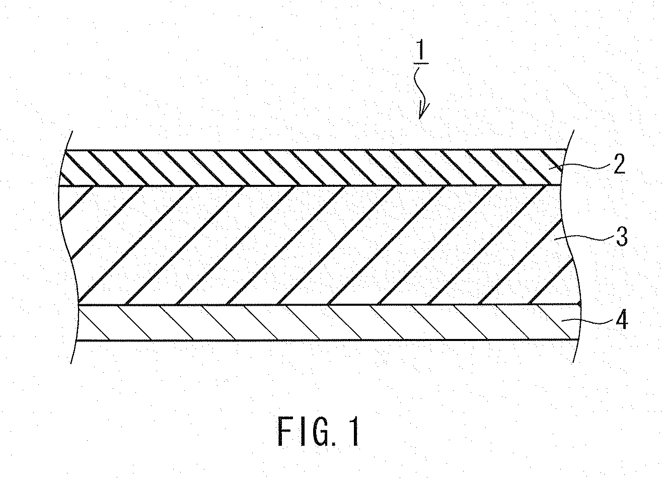
[0151]Using a blade coater, the negative electrode mixture-containing slurry of Example 1 and the slurry for forming a coating layer were applied onto the both surfaces of a current collector composed of a copper foil having a thickness of 8 μm such that the negative electrode mixture-containing slurry of Example 1 served as the lower layer and the slurry for forming a coating layer served as the upper layer. Then, the current collector was dried at 100° C., and then compression molded by a roller press so as to form laminates each including a negative electrode mixture layer having a thickness of 35 μm and a coating layer having a thickness of 5 μm on the both surfaces...
example 3
[0153]200 g of SiO (average particle size: 1 μm), 60 g of graphite (average particle size: 3 μm) and 30 g of polyethylene resin particles as a binder were placed in a container made of stainless steel and having a capacity of 4 L, and the container was further placed in a bowl made of stainless steel, and the SiO, the graphite and the polyethylene resin particles were mixed, pulverized, and granulated for 3 hours using a vibrating mill. As a result, composite parades (composite particles of SiO and graphite) having an average particle size of 20 μm were prepared. Then, the composite parades were heated to about 950° C. in an ebullated bed reactor to bring the heated composite particles into contact with a mixed gas of toluene and a nitrogen gas with a temperature of 25° C. for CVD treatment at 950° C. for 60 minutes. In this way, the carbon produced by thermal decomposition of the mixed gas was deposited onto the composite particles to form a coating layer thereon. Thereby, a negati...
PUM
| Property | Measurement | Unit |
|---|---|---|
| thickness | aaaaa | aaaaa |
| temperature | aaaaa | aaaaa |
| temperature | aaaaa | aaaaa |
Abstract
Description
Claims
Application Information
 - R&D
- Intellectual Property
- Life Sciences
- Materials
- Tech Scout
- Unparalleled Data Quality
- Higher Quality Content
- 60% Fewer Hallucinations
Browse by: Latest US Patents, China's latest patents, Technical Efficacy Thesaurus, Application Domain, Technology Topic, Popular Technical Reports.
© 2025 PatSnap. All rights reserved.Legal|Privacy policy|Modern Slavery Act Transparency Statement|Sitemap|About US| Contact US: help@patsnap.com


