Developing device and image forming apparatus using the same

Active Publication Date: 2010-08-05
SHARP KK
View PDF7 Cites 4 Cited by
  • Summary
  • Abstract
  • Description
  • Claims
  • Application Information

AI Technical Summary

Benefits of technology

[0013]The present invention has been devised in view of the above problems, it is therefore an object of the present invention to provide a developing device that is excellent in agitating the developer without excessively raising stress on the developer as well as providing an image forming apparatus using this device.

Problems solved by technology

However, this configuration has suffered the problem that if the helical pitch of the auger screw is made greater or the rotational speed of the augers is increased in order to raise the speed of developer conveyance, the pressure acting from the helical blade on the developer becomes higher, causing stress on the developer and hence lowering developer fluidity seriously.
As a result, this configuration has suffered the problem that variation in toner concentration across the length of the auger screw cannot be leveled off, causing toner density unevenness.
Further, when a conveying member provided with a plurality of discrete agitating blades is used in order to enhance agitation performance of the developer, this configuration has suffered the problem that the flow of the developer is made unstable, causing stress on the developer and hence markedly lowering developer fluidity.

Method used


Image

  • Developing device and image forming apparatus using the same
  • Developing device and image forming apparatus using the same
  • Developing device and image forming apparatus using the same

Examples


first embodiment

The First Embodiment

[0052]Now, the embodied modes for carrying out the present invention will be described with reference to the drawings.

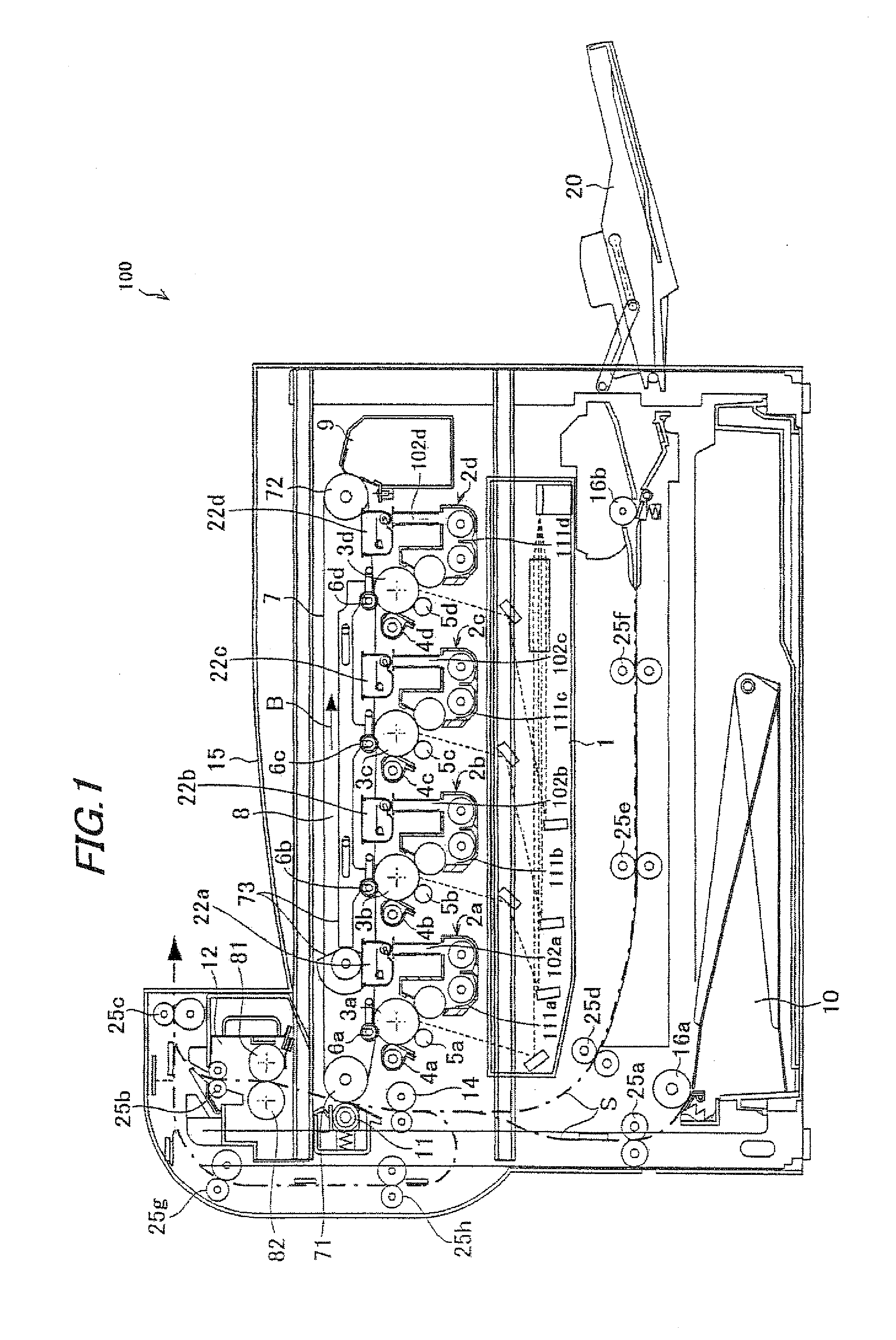
[0053]FIG. 1 shows one exemplary embodiment of the present invention, and is an illustrative view showing the overall configuration of an image forming apparatus in which developing devices according to the first to third embodiments are used.

[0054]An image forming apparatus 100 of the present embodiment forms an image with toners based on electrophotography, including: as shown in FIG. 1, photoreceptor drums 3a, 3b, 3c and 3d (which may be also called “photoreceptor drums 3” when general mention is made) for forming electrostatic latent images on the surface thereof; chargers (charging devices) 5a, 5b, 5c and 5d (which may be also called “chargers 5” when general mention is made) for charging the surfaces of photoreceptor drums 3; an exposure unit (exposure device) 1 for forming electrostatic latent images on the photoreceptor drum 3 surfaces; de...

second embodiment

The Second Embodiment

[0144]A developing device 2X according to the second embodiment will be described with reference to the drawings.

[0145]FIG. 8 is a sectional view showing the configuration of developing device 2X, FIG. 9 is a sectional view cut along a plane A3-A4 in FIG. 8, and FIG. 10 is a sectional view cut along a plane B3-B4 in FIG. 8.

[0146]As shown in FIG. 8, developing device 2X has a developing roller 114 arranged in developing vessel 111 so as to oppose photoreceptor drum 3 and supplies toner from developing roller 114 to the photoreceptor drum 3 surface to visualize (develop) the electrostatic latent image formed on the surface of photoreceptor drum 3.

[0147]Developing device 2X, other than developing roller 114, further includes developing vessel 111, a developing vessel cover 115, a toner supply port 115a, a doctor blade 116, a first conveying member 112X, a second conveying member 113X, a partitioning plate 117 and a toner concentration detecting sensor 119.

[0148]As ...

third embodiment

The Third Embodiment

[0174]Next, the third embodiment for carrying out the present invention will be described with reference to the drawing.

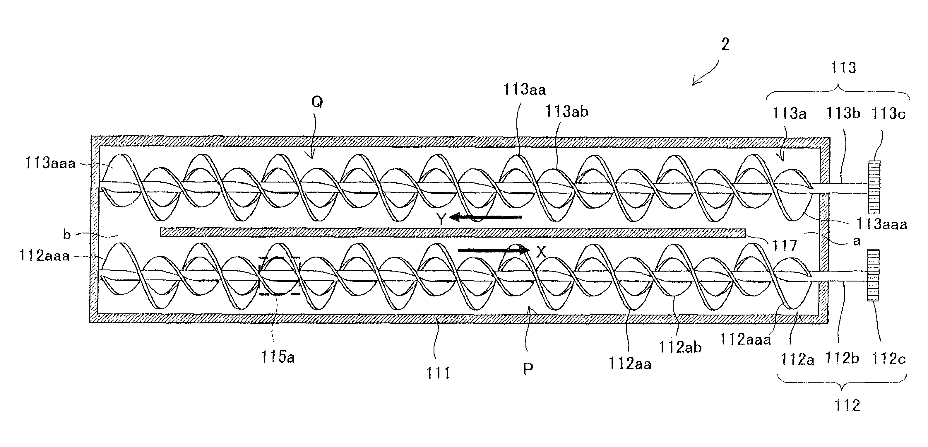
[0175]FIG. 11 is an illustrative view showing the configuration of a developing device 2Y according to the third embodiment of the present invention.

[0176]Here, since the configuration of developing device 2Y includes the same components as those of developing devices 2 and 2X of the first and second embodiments except the first and second conveying members, the same components are allotted with the same reference numerals and description on those is omitted.

[0177]As shown in FIG. 11, developing device 2Y has a developing roller 114 arranged in developing vessel 111 so as to oppose photoreceptor drum 3 and supplies toner from developing roller 114 to the photoreceptor drum 3 surface to visualize (develop) the electrostatic latent image formed on the surface of photoreceptor drum 3.

[0178]Developing device 2Y, other than developing roller 114, fur...


PUM


Abstract

A developing device includes a developing vessel for storing a developer, a first conveying passage, a second conveying passage, a first conveying member, a second conveying member and a developing roller for supplying toner to a photoreceptor drum. The first conveying member has a first rotary shaft and a first conveying blade formed on the periphery of the first rotary shaft. The first conveying blade has a large-diametric ring-shaped helical blade and a small-diametric helical blade, forming a double-helical structure. Alternatively, the first conveying blade is formed of helical blades being different in phase; each helical blade is formed so that the radius varies on a cycle of the rotational angle of 180 degrees.

Description

[0001]This Nonprovisional application claims priority under 35 U.S.C. §119 (a) on Patent Application No. 2009-021450 filed in Japan on 2 Feb. 2009 and Patent Application No. 2009-046112 filed in Japan on 27 Feb. 2009, the entire contents of which are hereby incorporated by reference.BACKGROUND OF THE INVENTION[0002](1) Field of the Invention[0003]The present invention relates to a developing device and an image forming apparatus using the device, in particular relating to a developing device using a dual-component developer containing a toner and a magnetic carrier, for use in an image forming apparatus for forming images using the toner based on electrophotography, such as an electrostatic copier, laser printer, facsimile machine or the like, as well as to an image forming apparatus using this device.[0004](2) Description of the Prior Art[0005]Conventionally, image forming apparatuses based on electrophotography such as copiers, printers, facsimile machines and the like have been k...

Claims


Application Information

Patent Timeline
IPC IPC(8): G03G15/08
CPCG03G2215/0822G03G2215/0833G03G2215/0838G03G15/0868G03G15/0879G03G15/0893G03G15/0875
Inventor MIHARA, KOICHIOHGOSHI, TOSHIHIDE
Owner SHARP KK
Why Eureka
Try Eureka