Dicing die-bonding film and process for producing semiconductor device
a technology of die-bonding film and semiconductor devices, which is applied in the direction of film/foil adhesives, solid-state devices, synthetic resin layered products, etc., can solve the problems of insufficient adhesion, difficult to balance the holding force at dicing and peeling ability at picking-up, and difficult to apply an appropriate amount of adhesive to the small wafer without damaging the wafer. , to achieve the effect of easy peeled, easy picking-up, and easy production o
- Summary
- Abstract
- Description
- Claims
- Application Information
AI Technical Summary
Benefits of technology
Problems solved by technology
Method used
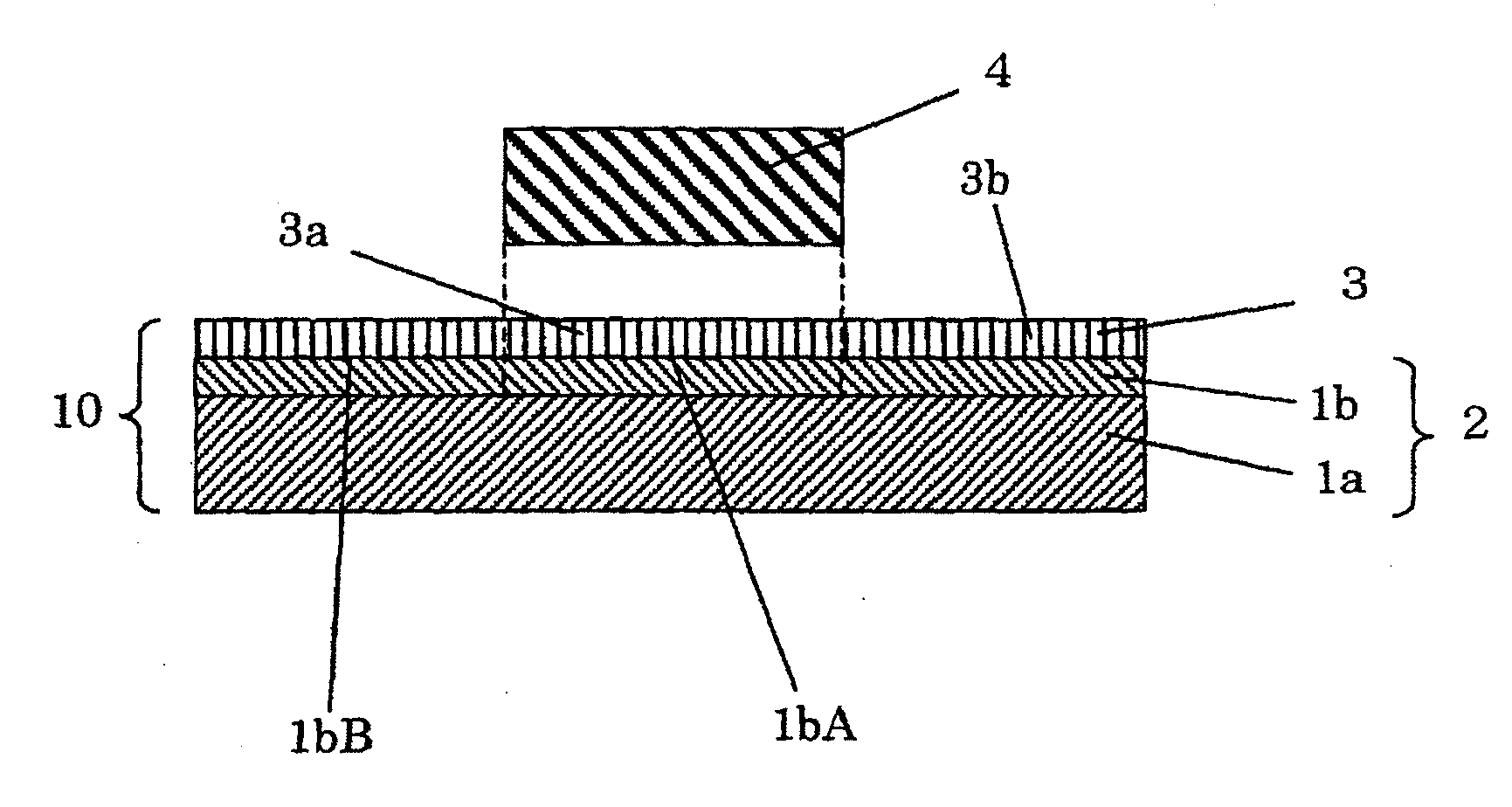
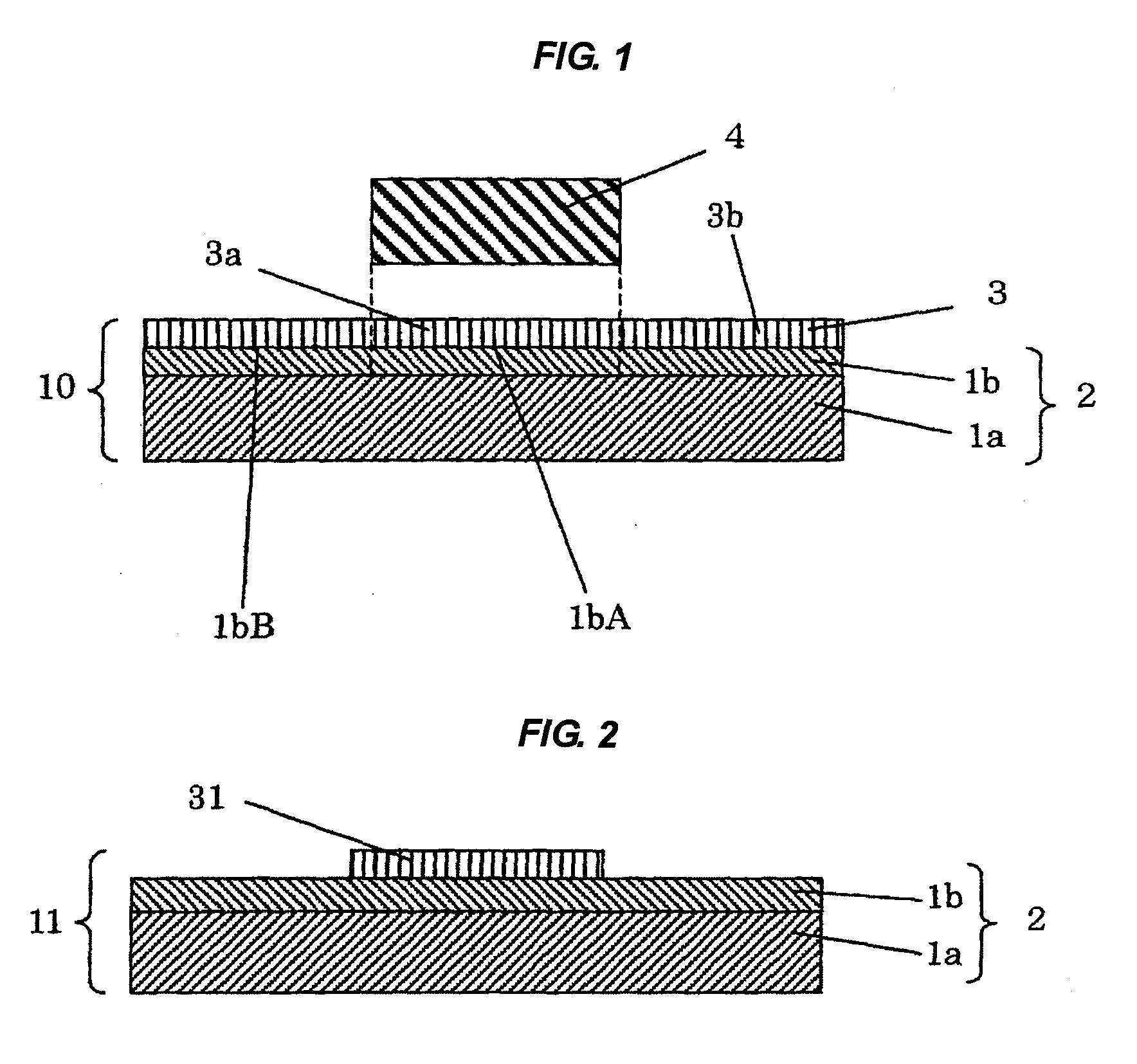
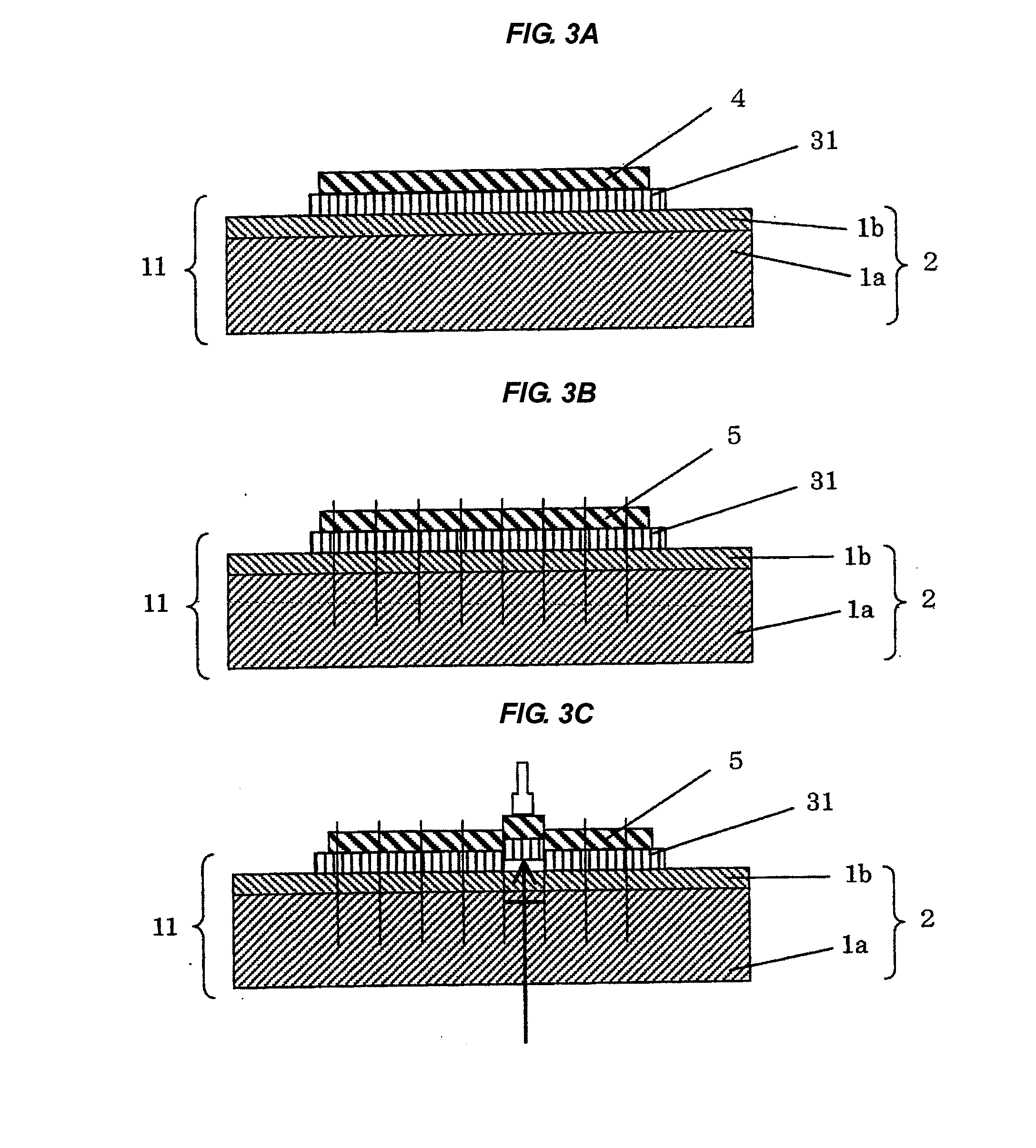
Image

Examples
example 1
Manufacture of Dicing Film
[0158]An acrylic polymer X was obtained by charging 95 parts of 2-ethylhexyl acrylate (hereinafter sometimes refers to as “2EHA”), 5 parts of 2-hydroxyethyl acrylate (hereinafter sometimes refers to as “HEA”), 0.2 part of benzoyl peroxide, and 65 parts of toluene into a reactor equipped with a condenser, a nitrogen introducing pipe, a thermometer, and a stirring apparatus, and performing a polymerization treatment at 61° C. for 6 hours under a nitrogen atmosphere.
[0159]Next, a pressure-sensitive adhesive solution was prepared by adding 8 parts of an isocyanate-based crosslinking agent (trade name “COLONATE L” manufactured by Nippon Polyurethane Industry Co., Ltd.) and 80 parts of a gas-generating agent (trade name “VAm-100” manufactured by Wako Pure Chemical Industries, Ltd.) to 100 parts of the acrylic polymer X.
[0160]A pressure-sensitive adhesive layer having a thickness of 10 μm was obtained by applying the pressure-sensitive adhesive solution prepared a...
examples 2 to 5
[0163]A dicing die-bonding film was manufactured in each of Examples 2 to 5 in the same manner as in Example 1 except that the dicing film was changed to a dicing film having the composition and the content (the composition of the base polymer of the pressure-sensitive adhesive, the content of the crosslinking agent, the content of the gas-generating agent, etc.) shown in Table 1.
example 6
[0164]A dicing die-bonding film was manufactured in Example 6 in the same manner as in Example 1 except that the composition of the base polymer, the crosslinking agent, and the amount of the gas-generating agent were changed to those described in Table 1 and additionally 20 parts of a terpenephenol-based resin (trade name “PR-12603” manufactured by Sumitomo Bakelite Co., Ltd.) was added.
PUM
| Property | Measurement | Unit |
|---|---|---|
| Temperature | aaaaa | aaaaa |
| Length | aaaaa | aaaaa |
| Percent by mass | aaaaa | aaaaa |
Abstract
Description
Claims
Application Information
 - R&D Engineer
- R&D Manager
- IP Professional
- Industry Leading Data Capabilities
- Powerful AI technology
- Patent DNA Extraction
Browse by: Latest US Patents, China's latest patents, Technical Efficacy Thesaurus, Application Domain, Technology Topic.
© 2024 PatSnap. All rights reserved.Legal|Privacy policy|Modern Slavery Act Transparency Statement|Sitemap