Plain bearing

Active Publication Date: 2010-05-27
TAIHO INDUSTRIES CO LTD
View PDF15 Cites 3 Cited by
  • Summary
  • Abstract
  • Description
  • Claims
  • Application Information

AI Technical Summary

Benefits of technology

[0045]The plain-bearing alloy according to the present invention contains Sn and Ni. Sn and Ni lower activity of Cu and hence suppress diffusion of Cu into the Sn-based overlay. Sn and Ni strengthen copper alloy and enhance its fatigue resistance. Sn and Ni also solution-harden the copper alloy. When the total content of Sn and Ni is less than 4 mass %, they are effective only to an unsatisfactory level. On the other hand, when the total content exceeds 20 mass %, the copper alloy is excessively solution hardened, thereby impairing seizure resistance at offset contact. Total content is preferably 4 to 12 mass %, and more preferably 5 to 8 mass %. Sn and Ni are essentially equally effective for the points described above. However, Sn must be present in an amount of at least 4 mass %, in view of decreasing Cu activity and enhancing fatigue resistance.

Problems solved by technology

Therefore, Sn, which is usually contained in the copper alloy, is not indispensable.
In addition, an Ni intermediate layer interposed between the overlay and plain bearing for preventing diffusion of Sn is also not indispensable.
Therefore, an Ni intermediate layer between the overlay and plain bearing for preventing diffusion of Sn is not indispensable for preventing diffusion of Sn.

Method used


Image

  • Plain bearing
  • Plain bearing
  • Plain bearing

Examples


example 1

[0088]Composition of a lining is shown in Table 1. A 1.5 mm thick plain bearing was produced by conventional rolling and forming. Sheet material was subjected to electrolytic degreasing, water rinsing, pickling, and water rinsing. A 10 μm thick overlay was deposited on the sheet material by electro-plating. The conditions for electro-plating were as follows. Identical results were obtained.

[0089]Condition (a):

[0090]Stannous sulfate: 20-30 g / L (in terms of metallic Sn)

[0091]Inorganic ammonium salt: 50-150 g / L

[0092]Organic Carbonic acid: 10-40 g / L

[0093]Bath temperature: 30 degrees C.

[0094]Current density: 0.5 to 5 A / dm2

[0095]Condition (b)

[0096]Sn fluoroborate: 10-20 g / L (in terms of Sn ions)

[0097]Fluoroboric acid: 100-500 g / L

[0098]Gelatin: 0.5-4 g / L

[0099]β naphthol: 0.1-2 g / L

[0100]Bath temperature: 30 degrees C.

[0101]Current density: 0.5-5 A / dm2

[0102]All of the specimens were subjected to heating at 150 degrees C. for 1000 hours, thereby providing a final operating condition of an a...

example 2

[0107]With regard to examples Nos. 1, 2 and comparative examples Nos. 1, 3, the heat treatment was carried out at 200 degrees C. for 5 hours. Then, the seizure resistance test was carried out. The results are shown in Table 2.

TABLE 2ClassificationTest Specimen No.Seizure ResistanceInvention1: Cu—4Sn—0.01Ni72 MPa2: Cu—7Sn—3Ni80 MPaComparative Example1: Cu24 MPa2: Cu—2Sn20 MPa

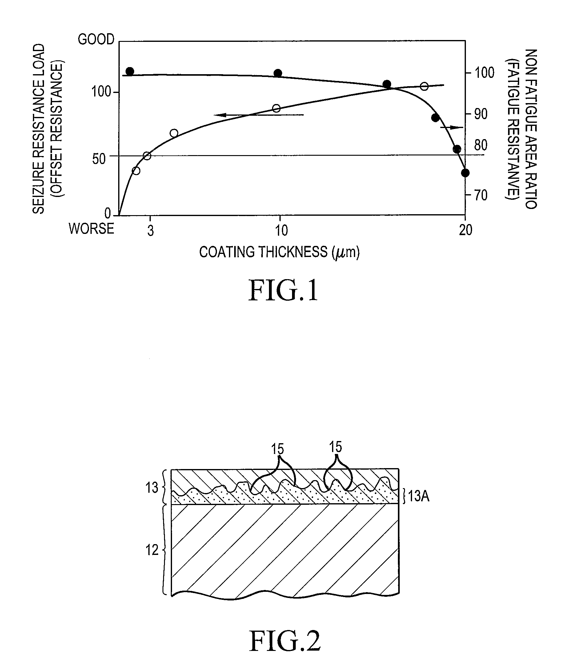
[0108]Seizure resistance of Test Specimens 1, 2 is further improved over that in Example 1. This indicates that a Cu—Sn diffusion layer having minute convexities effectively enhance seizure resistance. The Cu—Sn diffusion layer is 3 μm thick.


PUM

PropertyMeasurementUnit
Lengthaaaaaaaaaa
Timeaaaaaaaaaa
Percent by massaaaaaaaaaa

Abstract

The copper alloy (lining) prevails in an overwhelmingly large amount in a plain-bearing layer structure. Cu of the plain bearing copper-alloy diffuses into the Sn-based overlay diffuses into the Sn-based overlay and detrimentally impairs the performance of the overlay. The present invention takes a measure against this problem. An Sn-based overlay having a thickness of 3 to 19 μm is deposited by electro-plating without an intermediate layer for diffusion prevention on a plain-bearing layer, which contains Sn and Ni in a total amount of more than 4 mass % to 20 mass % (the minimum amount of Sn is 4 mass %) and has a hardness of Hv 150 or less.

Description

TECHNICAL FIELD[0001]The present invention relates to a plain bearing. More particularly, an Sn-based overlay is applied on a copper-based alloy layer of the plain bearing, in order to satisfy compatibility requirements. The present invention relates to a technique for preventing performance deterioration of the Sn-based overlay due to diffusion of Cu from the copper-based alloy layer into the same.BACKGROUND TECHNIQUE[0002]Heretofore, copper alloys with soft alloying additives such as Pb and Bi (referred to as “lining”) have been used for the plain bearing described above. Metallic Pb or Sn or their alloys have been used for the overlay. Cu of the copper alloy diffuses into the overlay and forms Cu—Sn based intermetallic compounds such as Cu6Sn5, Cu3Sn, and the like, which in turn deteriorate fatigue resistance and softness of the overlay.[0003]Therefore, an intermediate metallic layer, such as an Ni intermediate layer referred to as an Ni barrier, is usually interposed between the...

Claims


Application Information

Patent Timeline
IPC IPC(8): F16C17/00
CPCC22C9/00C22C9/02C22C13/00C22C13/02F16C2204/12F16C33/121Y10T428/12472Y10T428/12715F16C33/12
Inventor SUGA, SHIGEYUKIWADA, HITOSHITOMIKAWA, TAKASHI
Owner TAIHO INDUSTRIES CO LTD
Why Eureka
Try Eureka