Method and apparatus for producing tire inner liner members, and tire having inner liner

a technology of inner liner and tire, which is applied in the field of method and apparatus for producing tire inner liner members and tire having inner liner, can solve the problems of uneconomically increasing the amount of rubber strips used, reducing the durability performance, and reducing the work necessary to cut these unnecessary portions. , to achieve the effect of suppressing the generation of building failure and product failur

Inactive Publication Date: 2010-05-27
TOYO TIRE & RUBBER CO LTD
View PDF6 Cites 9 Cited by
  • Summary
  • Abstract
  • Description
  • Claims
  • Application Information

AI Technical Summary

Benefits of technology

[0015]By this configuration, it is ensured that the cut strip pieces can be joined together on the liner forming drum, and due to this, no bonding failure occurs and there is caused no fear that separation is generated even when the drum is expanded in the tire building process. In addition, since the winding initiating side end portion and the winding terminating side end portion of the spiral winding can be joined together while being superposed on each other on the building drum, no unnecessary portion is produced in the winding initiating side end portion and the winding terminating side end portion in building, whereby the cutting treatment of the end portions which occurs when the rubber strip is wound spirally directly round the expandable building drum in the tire building process can be made unnecessary, thereby making it possible to suppress the waste of the rubber material.
[0017]By this configuration, only by performing the cutting in the one location after the spiral winding has been completed, the sheet-shaped inner liner member which can be affixed to the building drum in the tire building process can be produced, and both the winding initiating side and winding terminating side end portions of the spiral winding can be superposed on each other as joint margins so as to be joined together. In particular, since the superposing amount of both the end portions which constitute the joint margins in joining them together on the building drum can be adjusted, the width of the rubber strip and the pitch of the spiral winding can be set as required, and thereby flexibility according to tire sizes can be secured.
[0019]In the inner liner member producing method, the ribbon-shaped rubber strip is wound spirally in such a manner as to be overlapped on itself one half or more of a strip width, so that the rubber strip is wound in two or more layers except for both the winding initiating side end portion and the winding terminating side end portion thereof. As this occurs, the inner liner member can be formed in two or more layers as a whole through the single spiral winding except for the winding initiating side and winding terminating side end portions, and moreover, since the inner liner member can be made to be made up of two or more layers also at both the end portions by superposing them on each other for joining, a joint can be made where the two or more layers are secured without increasing excessively the number of times of winding.
[0021]The method described above can easily be implemented by using the apparatus described above, whereby the rubber strip spirally wound round the liner forming drum can be joined to itself by allowing the rubber strip to be overlapped substantially uniformly over the whole length thereof in an ensured fashion, and moreover, after the spiral winding, the cylindrical body so formed can be cut in the location where the slit is formed. Furthermore, in the apparatus, in the case of the supporting table being separately provided on which the sheet-shaped member which results after the spirally wound cylindrical body has been cut can be placed in a deployed state, by placing the sheet-shaped member which results from the cutting described above thereon in the deployed state, the sheet-shaped member can be shaped into a normal sheet shape, and is turned to change its vertical and horizontal directions so as to be affixed to the building drum with its cut edges oriented in the tire circumferential direction for ease of the building.
[0025]By this configuration, since the strip pieces which make up the inner liner member are aligned substantially in the same direction as that of mainly the ply cords which are aligned in the radial direction in the carcass layer which is laminated thereof, the direction of the strip pieces becomes identical relative to the elongation of the tire in the radial direction thereof and the divergence of the cords in the circumferential direction, whereby the quality of the tire is held properly. In addition, since portions where a difference in level is caused by the overlap of the strip pieces and irregularities caused by the ply cords does not cross each other, no air reservoir is produced, thereby making it possible to suppress the generation of a building failure and product failure.BEST MODE FOR CARRYING OUT THE INVENTION
[0042]In addition, since the strip pieces 21A which are cut in the way described above are such that the strip pieces 21A are spirally wound in such a manner as to be inclined to some extent relative to the circumferential direction and are then cut in the width direction, the strip pieces 21A are aligned at substantially right angles or close to right angles to the circumferential direction and are aligned in the same direction as that of the ply cords in the carcass layer which is affixed and laminated thereon, that is, are basically aligned in the same direction as the cords aligned in the radial direction. Due to this, since the direction of the strip pieces 21A becomes identical relative to the elongation of the tire in the radial direction thereof and the divergence of the cords in the circumferential direction and portions where a difference in level is caused by the overlap of the strip pieces 21A and irregularities caused by the ply cords does not cross each other, no air reservoir is produced, thereby making it possible to suppress the generation of a building failure and product failure.

Problems solved by technology

In the event, however, that the inner liner, which constitutes an innermost layer, is built by winding spirally a ribbon-shaped rubber strip on the expandable drum as described in Patent Document No. 1, oblique unnecessary portions are produced at an end portion on a winding initiating side and an end portion on a winding terminating side, and work to cut these unnecessary portion is necessary.
In this case, the unnecessary portions at both the end portions need to be cut off, and moreover, the amount of rubber strip used is uneconomically increased.
In addition, since joining portions where the rubber strip is joined to itself as a result of the rubber strip being overlapped on itself while being wound spirally exist continuously in the circumferential direction of the tire, there is a fear that the joined portions are disjoined when expanded in the building process to thereby produce non-bonded portions, which is not preferable from the viewpoint of durability performance of the tire.
Furthermore, the winding initiating side end portion and the winding terminating side end portion come to be situated underneath the bead portions, thereby causing a fear that the tire balance accuracy is deteriorated.
In particular, in the event that the strip pieces are aligned on the expandable building drum for joining, since the building drum has gaps between drum pieces for allowing for the expansion and contraction of the building drum, the strip pieces cannot be bonded together completely in the portions where the gaps are provided, and as a result, there is caused a fear that a production failure is produced such as separation, air mixing or the like.

Method used


Image

  • Method and apparatus for producing tire inner liner members, and tire having inner liner
  • Method and apparatus for producing tire inner liner members, and tire having inner liner
  • Method and apparatus for producing tire inner liner members, and tire having inner liner

Examples


Embodiment Construction

[0026]Next, a mode for carrying out the invention will be described based on an embodiment shown in drawings.

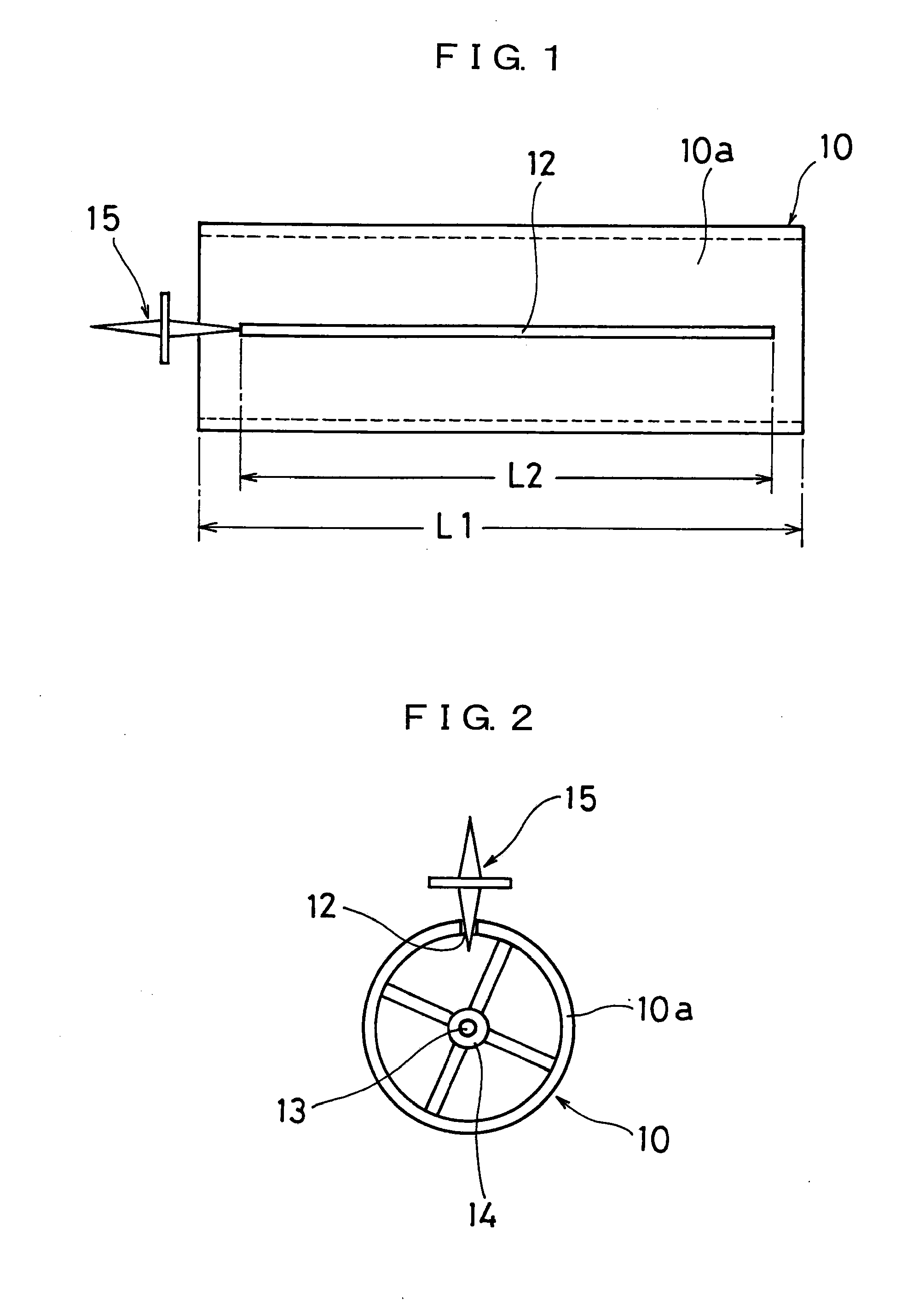
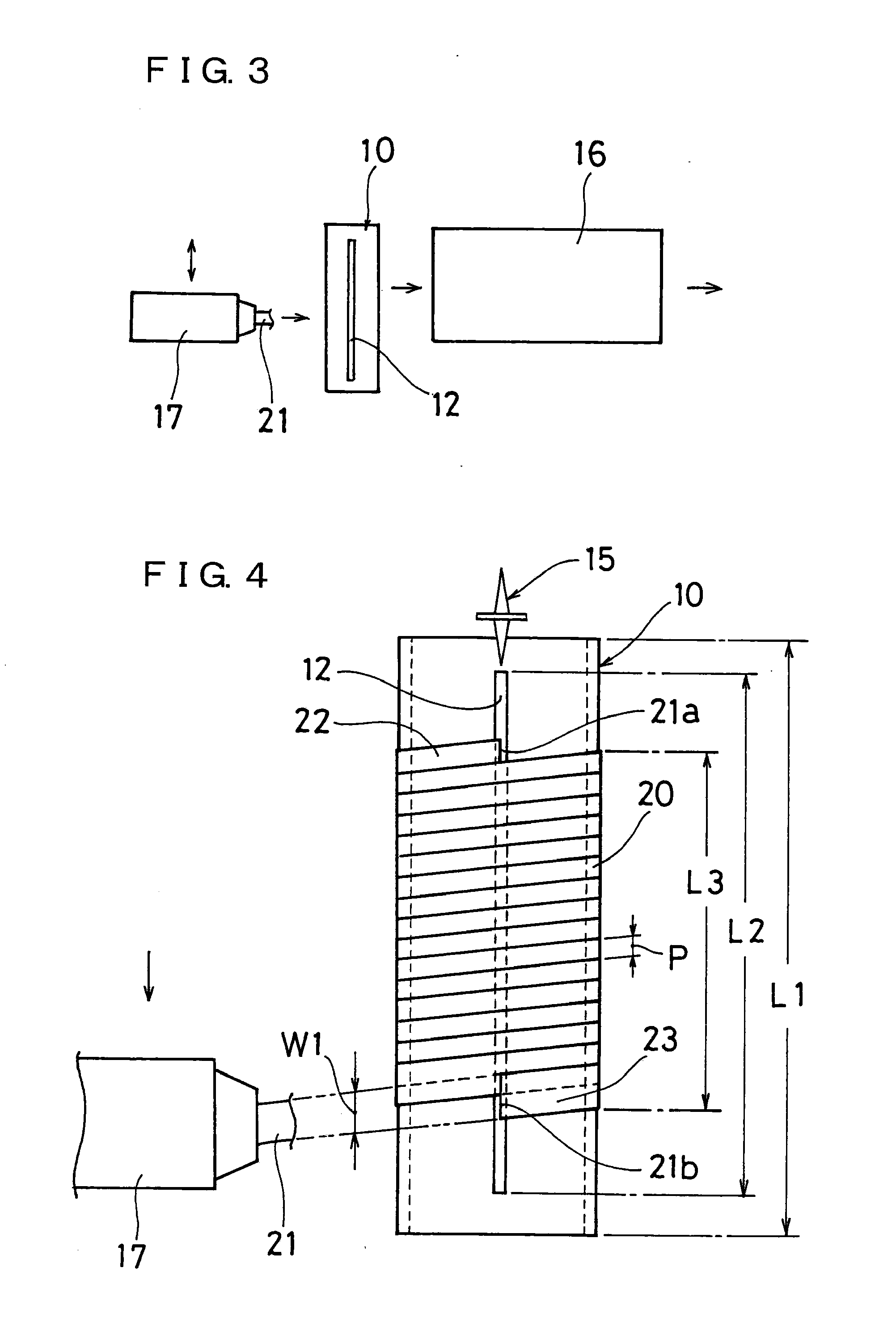
[0027]FIGS. 1 and 2 show schematically a liner forming drum 10 and a severing cutter 15 which are main members of a producing apparatus which is used in implementing an inner liner member producing method of the invention.

[0028]The liner forming drum 10 which is used in the invention is made up of a cylindrical drum in which its axial length L1 is longer than a circumferential length of an inner liner member which is to be produced on a building drum in a tire building process and its circumferential length corresponds to a lateral width of the inner liner member on the building drum and which is a normal drum which is neither expanded nor contracted. A cutting slit 12, which is slightly longer than the circumferential length L2 of the inner liner member to be produced and is slightly shorter than the axial length L1 of the drum 10, is formed in the drum 10 in a location in a...


PUM

PropertyMeasurementUnit
Currentaaaaaaaaaa
Lengthaaaaaaaaaa
Widthaaaaaaaaaa

Abstract

A process for producing easily in high efficiency an inner liner having strip pieces obtained by cutting a ribbonlike rubber strip at given length arranged in parallel relationship in the across-the-width direction, aligned in the direction of tire circumference and bonded together. The process comprises spirally winding ribbonlike rubber strip (21) round liner forming drum (10) at given pitch so as to make partial superimposition, thereby obtaining tubular matter (20), and cutting the tubular matter (20) at one position on the circumference thereof in the across-the-width direction so as to provide a sheet wherein severed strip pieces (21A) are bonded to each other in the state of being aligned in parallel relationship, having a length corresponding to the length of liner circumference on a forming drum in the tire forming step, and wherein the two ends on the starting side and terminating side of the spirally winding can be joined together on the forming drum.

Description

TECHNICAL FIELD[0001]The present invention relates to a method and apparatus for producing tire inner liner members, and a tire having an inner liner.BACKGROUND ART[0002]In general, tires are made up of a plurality of tire constituent members. For example, as is shown in FIG. 10, an inner liner 2, a tread 3, side walls 4, rim strips 5 and the like are formed of rubber members which are prepared according to properties required therefor, respectively, and these rubber members are combined with tire reinforcement members such as carcass layers 6 and belt layers 7 which include cords so as to make up a tire T. In the figure, reference numeral 8 denotes a bead portion which includes a bead core 9.[0003]Conventionally, to built the respective rubber members, rubber members were extruded via dies which match cross-sectional shapes of the rubber members, and thereafter, the extruded rubber members were cut to predetermined dimensions so as to obtain target rubber members. In building a tir...

Claims


Application Information

Patent Timeline
IPC IPC(8): B60C5/00B29D30/08
CPCB29D30/0681B29D30/3028Y10T152/10495B60C5/14B29D2030/0682
Inventor KUDO, SHIGEOTATARA, TETSUOFUJIKI, OSAMU
Owner TOYO TIRE & RUBBER CO LTD
Why Eureka
Try Eureka