
Aluminum alloy composite and method for joining thereof

a technology of aluminum alloy and composites, applied in the field of aluminum alloy composites and joining, can solve the problems of laborious work, not so much growth in use as a civilian aircraft material, and not so much growth in the use of aircraft material as anticipated

Active Publication Date: 2010-04-22
TAISEI PLAS CO LTD
View PDF8 Cites 39 Cited by
  • Summary
  • Abstract
  • Description
  • Claims
  • Application Information

AI Technical Summary

Benefits of technology

[0024]A further object of the present invention is to provide an aluminum alloy composite and a method for manufacturing the same, which enable a CFRP material and an aluminum alloy part to be joined without using a fastening means such as a bolt and nut having a special construction, that is, which enables such joining to be carried out with ordinary fastening means.

Problems solved by technology

Up until now, the utilization of CFRP as a material for aircraft has been increased in military applications such as fighter planes and combat helicopters, while use as a civilian aircraft material has not grown so much as anticipated due to the need to develop know-how on manufacturing large components and because of obstacles from the standpoint of cost.
Although significant advances have been made in the development of fuel cells, the largest and most difficult problem that remains for use in automobiles is how to safely and smoothly handle hydrogen fuel, for which laborious work has been made.
While safety is most important in civilian use, the obstacles are too large to make it a routine matter for general users to deal with cars loaded with hydrogen gas under several hundred atmospheres of pressure.
In aircraft manufacture, the increased utilization of CFRP materials entails an increase in material expenses due to the high-cost CFRP materials, in addition to which it presents technical problems.
One such problems is that, even in the latest Airbus and Boeing aircraft for which mass production has already been decided, it is estimated that the utilization of aluminum alloys will top 50% in terms of weight, with both CFRP materials and A7075 materials being used.
However, when a compressive load is applied to CFRP, the force is first supported by the cured epoxy resin; with the application of an excessive pressing force, the epoxy resin is forced to spread peripherally and be deformed but spreading is limited by the carbon fibers, as a result of which the resin does not move and thus cannot be deformed, leading ultimately to failure.
Because the large differences between the physical properties of both materials are due to inherent differences between a metal part, which is composed of metallic bonds between atoms, and epoxy resins and carbon fibers, which are composed of covalent bonds between carbon atoms and the like, there are basically no means for improving the properties themselves.
There is another problem as to releasing of the CFRP prepreg from the metallic mold after its heat-curing.
As a result, infiltration of the release agent (generally a silicone oil-type release agent) into the CFRP product is unavoidable, which makes it impossible to achieve the highest physical properties inherent to the epoxy resin.
Even minor decreases in quality are issues that must be resolved for use in structures for high-speed moving machinery such as aircrafts and automobiles.
However, it is actually difficult that cover 100% of an aluminum alloy surface in this way with such a rough surface, given the variability of chemical reactions.
Complete penetration of the epoxy adhesive to the depths of the fine depressions formed in the finely irregular surface of (2) is presumed to be difficult.
In such a case, the epoxy adhesive that has been cured inside a large depression achieves the state of being secured (engaged) at the interior of the depression by innumerable spikes, which should make it difficult to be peeled away from the metal substrate by an external force.
When the cured epoxy resin is forcibly peeled away, because the metal oxide layer of above-described condition (3) for the surface in contact with the spikes has a sufficient thickness to exhibit the hardness of this ceramic material, deformation on the metal alloy side is limited, making it impossible to pull out the epoxy resin within the large depression.
For depressions that are too small, penetration of the epoxy adhesive into the interior is probably insufficient.

Method used


Image

  • Aluminum alloy composite and method for joining thereof
  • Aluminum alloy composite and method for joining thereof
  • Aluminum alloy composite and method for joining thereof

Examples


working examples

Experiment Example 1

Adhesion with A5052 Aluminum Alloy

[0103]Commercially available A5052 sheet stock having a thickness of 1.6 mm was acquired and cut to form a plurality of rectangular pieces measuring 45×18 mm. Water was made ready in a tank and a commercially available aluminum alloy degreaser (NE-6, available from Meltex, Japan) was added to the water to form a aqueous solution of 60° C. having a concentration of 7.5%. The rectangular pieces of aluminum alloy were immersed in the solution for 7 minutes and then thoroughly rinsed with water. An aqueous solution of hydrochloric acid having a concentration of 1% and adjusted to 40° C. was made ready in another tank, in which the aluminum alloy pieces were immersed for 1 minute and then thoroughly rinsed with water. Next, an aqueous solution of caustic soda having a concentration of 1.5% and adjusted to 40° C. was made ready in still another tank, in which the same aluminum alloy pieces were immersed for 2 minutes and then thoroug...

experiment example 2

Adhesion with A5052 Aluminum Alloy

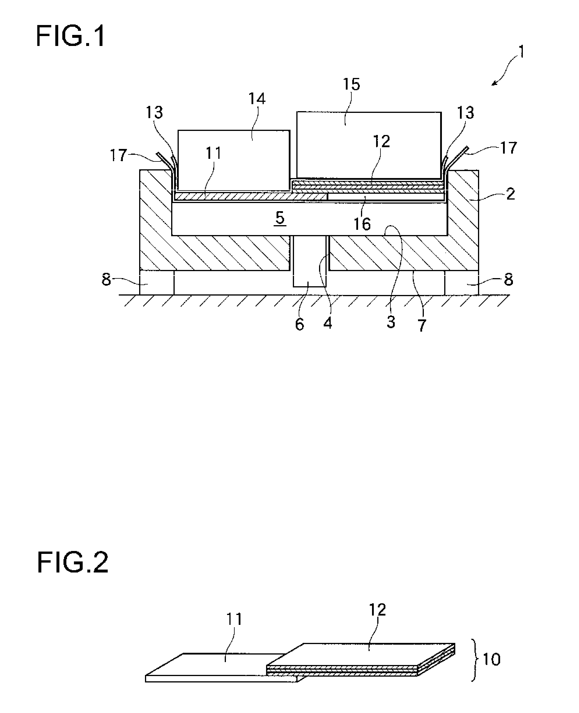
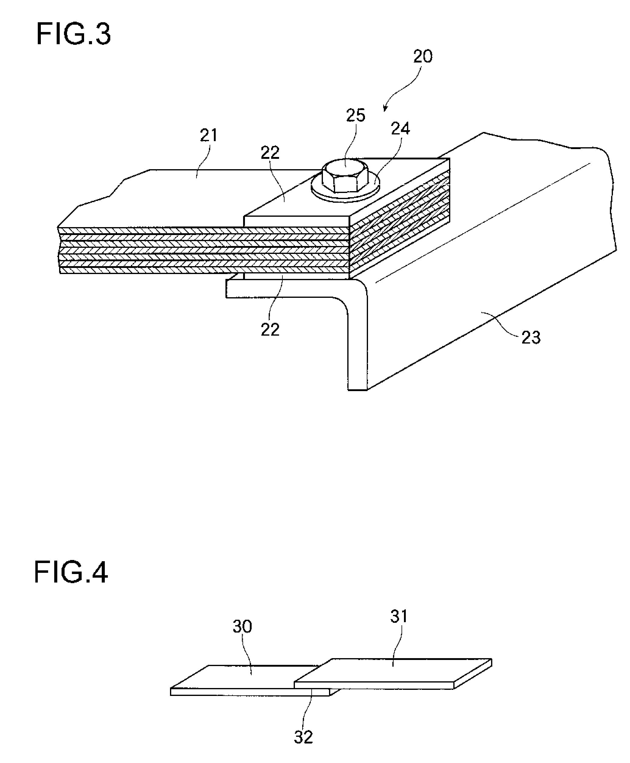
[0107]Surface treatment for pieces of A5052 plate was carried out in the same way as Experiment example 1. Up through treatment with the degreaser (NE-6, available from Meltex, Japan), preliminary pickling treatment with a 1%-aqueous solution of hydrochloric acid and alkali etching treatment with a 1.5%-aqueous solution of caustic soda, treatment was carried out in exactly the same as in Experiment example 1. Surface treatment ended at this point and the pieces were stored in the resulting state. The same day, these aluminum alloy pieces were taken out, the epoxy adhesive EP-106 was lightly coated on the ends and desiccation treatment, joining and curing of the adhesive in a hot-air dryer were subsequently carried out in exactly the same way as in Experiment example 1, yielding the test pieces shown in FIG. 4.

[0108]In tensile failure tests carried out two days later, the average shear strength at break for the four pairs was 48 MPa. These test piec...

experiment example 3

Adhesion with A5052 Aluminum Alloy

[0109]Pieces of A5052 plate were treated in the same way as Experiment example 1 up to a given point. Up through treatment with the degreaser NE-6, preliminary pickling treatment with a 1%-aqueous solution of hydrochloric acid, alkali etching treatment with a 1.5%-aqueous solution of caustic soda and neutralization treatment with a 3%-aqueous solution of nitric acid, treatment was carried out in exactly the same as in Experiment example 1. Surface treatment ended at this point and the pieces were stored in this state.

[0110]When these aluminum alloy pieces were subjected to XPS analysis, peaks for sodium were not observed, even cumulatively. Hence, sodium was concluded to have been removed by immersion in the aqueous nitric acid solution and rinsing with water. The same day, these aluminum alloy pieces were taken out, the epoxy adhesive EP-106 was lightly coated on the ends and desiccation treatment, joining and curing of the adhesive in a hot-air d...


PUM

PropertyMeasurementUnit
Percent by massaaaaaaaaaa

Abstract

The object of the present invention is to strongly join an aluminum alloy part with an FRP prepreg. An object obtained by subjecting an aluminum alloy to a suitable liquid treatment so as to form a surface having large, micron-order irregularities and also fine irregularities with a period of several tens of nanometers, eliminating the presence of sodium ions from the surface and additionally forming a surface film of aluminum oxide, which is thicker than a natural oxide layer, has been found to have a powerful adhesive strength with epoxy-based adhesives. By simultaneously curing an FRP prepreg which uses the same epoxy-based adhesive in the matrix, an integral composite or structure in which FRP and aluminum alloy have been united at a joining strength of unprecedented magnitude is produced.

Description

FIELD OF THE INVENTION[0001]The present invention relates to methods for joining metals with metals or metals with plastics that are used in transportation machinery, electrical equipments, medical instruments, general machinery, other industrial machinery, consumer equipments or the like; to composites thereof; and to methods for manufacturing the same. More specifically, the present invention relates to aluminum alloy composites and joining methods for integrally joining optimal aluminum alloy parts and plastic parts together, suitable for use as transportation machinery components that are required to be lightweight, such as automotive parts and aircraft parts.BACKGROUND OF THE INVENTION[0002]With the recent rise of energy prices, further technical innovations are being sought in aircraft. That is, in the new model aircraft and the new model concepts recently announced by the Boeing Company (U.S.) and Airbus (France), the utilization of aluminum alloys such as extra super duralum...

Claims


Application Information

Patent Timeline
IPC IPC(8): B32B3/02B32B5/08B44C1/22
CPCB32B7/12B32B15/08B32B27/04C09J163/00C23C22/83C23F1/36Y10T428/24355H05K3/383H05K3/385H05K3/386H05K2203/0315B32B38/08B32B43/00H05K1/056B32B5/024B32B5/08B32B5/147B32B15/14B32B15/20B32B27/38B32B2255/06B32B2255/26B32B2260/021B32B2260/046B32B2262/0269B32B2262/101B32B2262/106B32B2264/101B32B2264/102B32B2264/104B32B2264/107B32B2307/306B32B2307/54B32B2307/542B32B2307/714B32B2457/00B32B2605/00B32B2605/18Y10T428/31529Y10T428/31522Y10T428/24322Y10T428/265B32B3/30B32B15/092B32B9/00C23F1/16C23F1/32
Inventor NARITOMI, MASANORIANDOH, NAOKI
Owner TAISEI PLAS CO LTD
Learn More