Method for manufacturing soi substrate
a technology of soi and substrate, which is applied in the direction of semiconductor/solid-state device manufacturing, basic electric elements, electric apparatus, etc., can solve the problem of unlikely generation of surface unevenness due to dust, and achieve the effect of reducing the defects between bonding and sufficient bonding strength
- Summary
- Abstract
- Description
- Claims
- Application Information
AI Technical Summary
Benefits of technology
Problems solved by technology
Method used
Image
Examples
embodiment 1
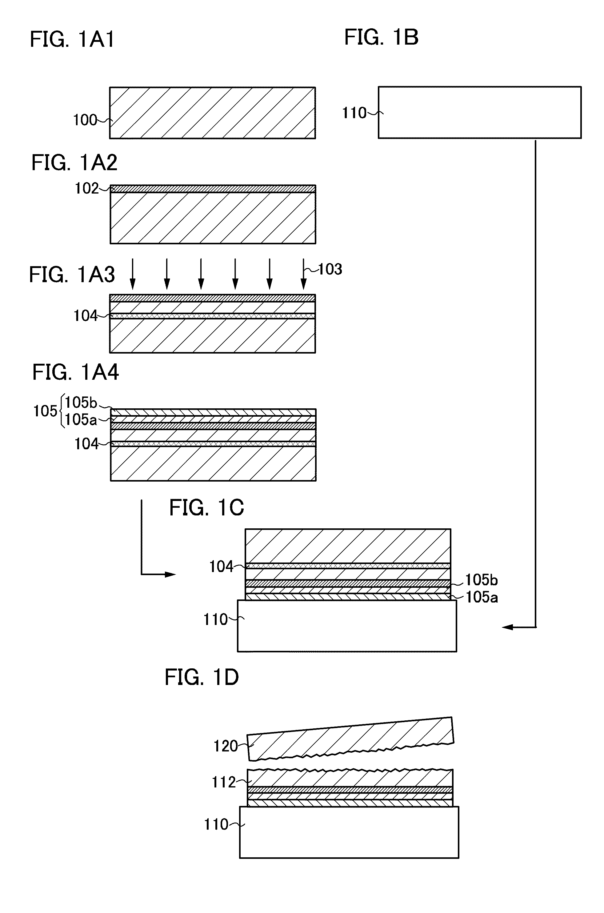
[0036]In this embodiment, a method for manufacturing a substrate provided with a semiconductor layer with an insulating film interposed therebetween (for example, an SOI substrate) by bonding a semiconductor substrate and a base substrate is described with reference to the drawings.
[0037]First, a single crystal semiconductor substrate 100 is prepared as a semiconductor substrate (see FIG. 1A1). The single crystal semiconductor substrate 100 can be a single crystal semiconductor substrate or a polycrystalline semiconductor substrate; for example, a single crystal or polycrystalline silicon substrate, a single crystal or polycrystalline germanium substrate, and a compound semiconductor substrate of gallium arsenide, indium phosphide, or the like can be used. The shape of a commercial silicon substrate is typically a circular shape, and the size thereof is typically 5 inches (125 mm) in diameter, 6 inches (150 mm) in diameter, 8 inches (200 mm) in diameter, 12 inches (300 mm) in diamet...
embodiment 2
[0110]In this embodiment, a method for manufacturing an SOI substrate which is different from that described in Embodiment 1 is described with reference to FIGS. 4A1 to 4D. Hereinafter, portions different from those in Embodiment 1 are described. Accordingly, a detailed description of portions similar to those in Embodiment 1 is omitted.
[0111]In this embodiment, preparation of a single crystal semiconductor substrate 100 (FIG. 4A1), a step for forming an insulating film 102 (FIG. 4A2), and an ion irradiation step (FIG. 4A3) can be performed in a manner similar to the preparation of the single crystal semiconductor substrate 100 (FIG. 1A1), the step for forming the insulating film 102 (FIG. 1A2), and the ion irradiation step (FIG. 1A3), in Embodiment 1, respectively.
[0112]Then, the insulating film 102 formed on the single crystal semiconductor substrate 100 is removed (see FIG. 4A4). Wet etching can be used for removing the insulating film 102. Alternatively, dry etching or chemical ...
embodiment 3
[0122]In this embodiment, a processing method of a single crystal semiconductor substrate in a case where a stacked-layer structure of an impurity semiconductor layer (a first impurity semiconductor layer) and a conductive layer is formed is described with reference to FIGS. 5A to 5G Note that a detailed description of the same portions as those in Embodiments 1 and 2 is omitted.
[0123]First, a single crystal semiconductor substrate 100 is prepared (see FIG. 5A). After the single crystal semiconductor substrate 100 is cleaned, an insulating film 102 is formed over a surface of the single crystal semiconductor substrate 100 (see FIG. 5B). Then, the single crystal semiconductor substrate 100 is irradiated with ions through the insulating film 102 to form an embrittlement region 104 in a region at a predetermined depth (see FIG. 5C). A detailed description of steps illustrated in FIGS. 5A and 5C is omitted because the steps can be performed in a manner similar to the steps illustrated i...
PUM
| Property | Measurement | Unit |
|---|---|---|
| thickness | aaaaa | aaaaa |
| diameter | aaaaa | aaaaa |
| diameter | aaaaa | aaaaa |
Abstract
Description
Claims
Application Information
 - R&D Engineer
- R&D Manager
- IP Professional
- Industry Leading Data Capabilities
- Powerful AI technology
- Patent DNA Extraction
Browse by: Latest US Patents, China's latest patents, Technical Efficacy Thesaurus, Application Domain, Technology Topic, Popular Technical Reports.
© 2024 PatSnap. All rights reserved.Legal|Privacy policy|Modern Slavery Act Transparency Statement|Sitemap|About US| Contact US: help@patsnap.com


