
Bone anchors for orthopedic applications

Inactive Publication Date: 2010-04-01
WARSAW ORTHOPEDIC INC
View PDF79 Cites 51 Cited by
  • Summary
  • Abstract
  • Description
  • Claims
  • Application Information

AI Technical Summary

Benefits of technology

[0008]In certain embodiments, the composite is capable of transitioning or transforming reversibly between different phase-states, e.g., from a substantially solid state to a malleable, moldable, pliable, or flowable state, back to a substantially solid state. In some embodiments, the composite transitions irreversibly between two phase-states, e.g., from a malleable, moldable, pliable, or flowable state to a substantially solid state. In certain embodiments, the composite is malleable under certain conditions, e.g., subjected to a high temperature or subjected to a certain solvent, and substantially rigid or solid under different conditions, e.g., subjected to a lower temperature, exposure to radiation, exposure to chemical reagent, subjected to evaporative conditions. The malleable composite can range in viscosity from a thick, flowable, or injectable liquid to a moldable, pliable, dough-like substance. In particular embodiments, phase-state transitions occur within biocompatible temperature ranges or biocompatible chemical conditions. In certain embodiments, an anchor formed from a malleable composite provides intimate contact with the irregular surfaces of the surrounding native bone.
[0010]In some embodiments, the inventive bone anchor is provided in a substantially solid state, comprising a solid composite, a solid plastic, a ceramic, a metal, or any combination thereof. A bone anchor provided in a substantially solid state can be provided as a preformed device. In certain embodiments, a preformed bone anchor can be made malleable or moldable by the addition of heat or a chemical additive. In some embodiments, the inventive bone anchor is provided in a non-preformed shape, which can be made malleable or moldable by the addition of heat or a chemical additive. When made malleable or moldable, the bone anchor can be adapted to fit into a void at a placement site and improve the integrity of bone at the placement site.
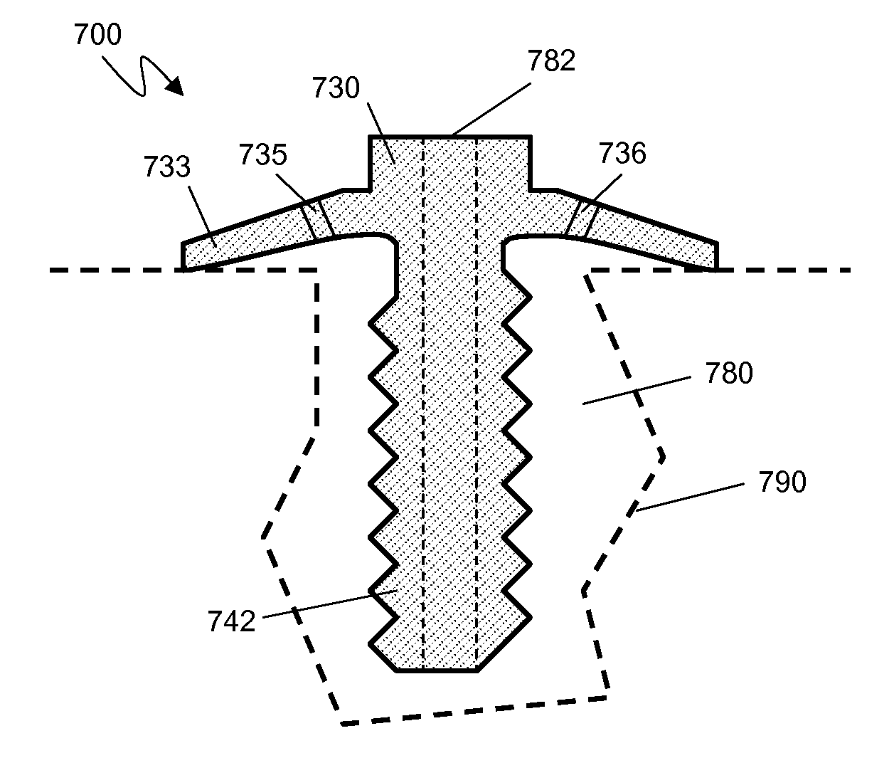
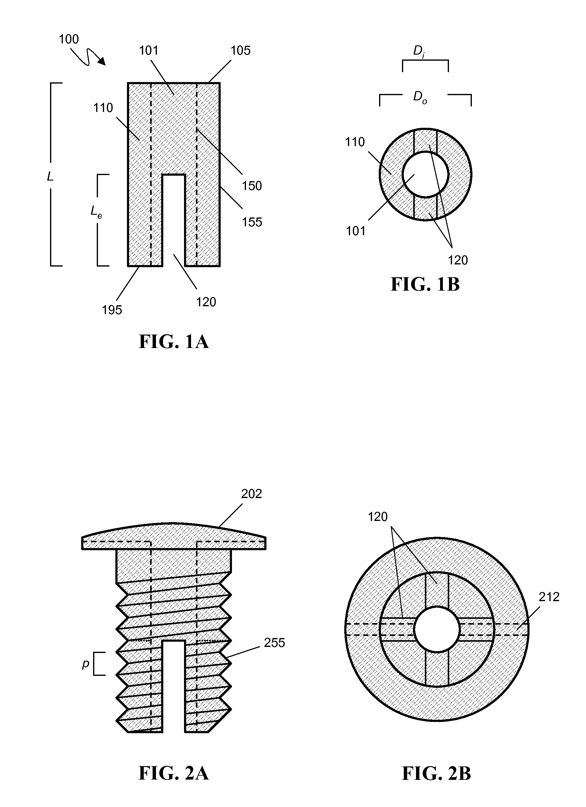
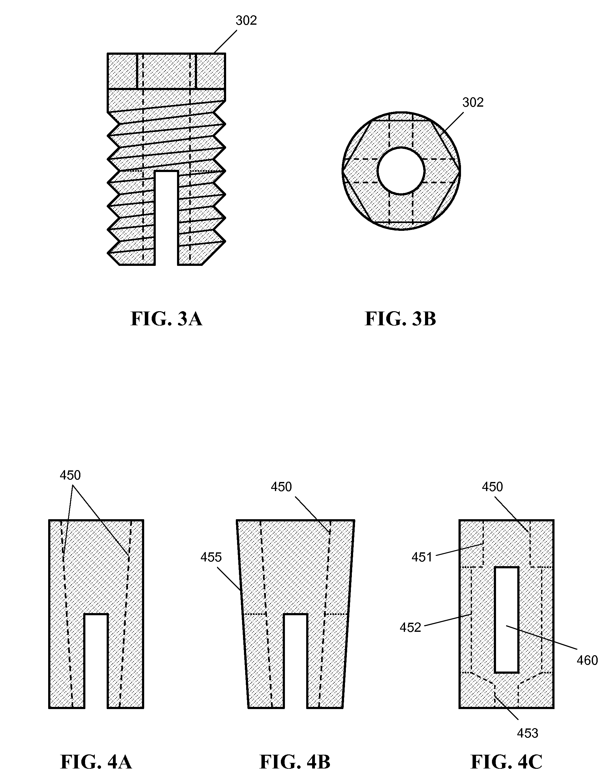
[0011]The inventive bone anchor can be formed into any of a variety of shapes. For example, bone-anchor shapes can include rods, cylinders, cones, rectangles, cubes, oval cylinders, partial cylindrical strips, tubes, polygonal tubes, and pyramids. In some embodiments, the bone anchor comprises a substantially cylindrically-shaped structure, optionally threaded on its outer surface. In some embodiments, the outer surface has grooves, ridges, ribs, protrusions, or the like which assist in holding the anchor securely at the implant site. The bone anchor can optionally contain a hollow center or core which can be threaded or without threads. In certain embodiments, the anchor comprises at least one slot permitting outward expansion of at least a portion of the anchor upon insertion of a fastening device into the anchor. In various embodiments, the bone anchor is tapered inward or outward on its outer surface, and is optionally tapered inward or outward on its inner surface. In some embodiments, the inner diameter of the anchor has at least two values along the axis of the anchor. In certain aspects, the bone anchor can be formed as pieces of a cylindrical tube, each individually implantable into a void in native bone to form in combination a bone anchor.
[0025]“Osteoinductive”: As used herein, the term “osteoinductive” is used to refer to the ability of a substance to recruit cells from the host that have the potential for forming new bone and repairing bone tissue. Most osteoinductive materials can stimulate the formation of ectopic bone in soft tissue.

Problems solved by technology

While bone wounds can regenerate without the formation of scar tissue, fractures and other orthopedic injuries take a long time to heal, during which the injured bone is unable to support physiologic loading.
However, metal is significantly stiffer than bone, and in some cases the bone cannot provide a secure, firm anchoring site for a metal fastener.
For example, osteoporotic bone has decreased density and may be unsuitable for anchoring metal or non-metal fasteners or other fixtures.
In some cases, the use of metal implants can cause a decrease in bone density around the implant site due to stress shielding.
A problem resulting from decreased bone density is pull-out of the metal fixture at the implant site.

Method used


Image

  • Bone anchors for orthopedic applications
  • Bone anchors for orthopedic applications
  • Bone anchors for orthopedic applications

Examples


Embodiment Construction

[0049]The present invention stems from the recognition that bone at a site of surgical intervention sometimes requires supplementation to provide adequate mechanical strength or integrity to meet the needs of the surgical intervention. As an example, a pedicle of the vertebra may require supplementation to securely receive and hold a pedicle screw. Bone at the site of surgical intervention, or placement site, can be normal bone, osteoporotic bone, cortical bone, cancellous bone, diseased bone, defective bone, deformed bone, bone which has undergone traumatic injury, bone needing revision from prior surgical intervention, or any combination thereof. Generally, the bone is unable to provide adequate mechanical support, anchoring or sufficient purchase for screws, fastening devices, or other medical devices which are to be attached to the bone. In such circumstances, a formable and solid-setting implantable bone anchor or preformed bone anchor would be a useful medical device to improv...


PUM


Abstract

Bone anchors and related methods for their use are described. The inventive anchor is suitable for placement in bone and for use in orthopedic surgery and dentistry. The bone anchor can be made from a bone / polymer or bone substitute / polymer composite, and can provide a firm and secure base for attaching a fastening device. The bone anchor can be used in various orthopedic and dental procedures including spinal surgery, where normal, cancellous, cortical, diseased or osteoporotic bone is present. The bone anchor can be resorbed and / or replaced with native bone tissue over a period of time. In certain embodiments, the bone anchor is made malleable or flowable and formed in situ or in vivo.

Description

CROSS-REFERENCE TO RELATED U.S. APPLICATIONS[0001]The present application claims priority under 35 U.S.C. §119(e) to U.S. provisional patent application, U.S. Ser. No. 61 / 040,483, filed on Mar. 28, 2008, which is incorporated herein by reference.FIELD OF THE INVENTION[0002]The invention pertains to implantable bone anchors useful in orthopedic surgery and dentistry. In particular, the bone anchors are made from bone / polymer composites or bone substitute / polymer composites, can be preformed prior to implantation or formed in situ, and can optionally expand upon insertion of a mechanical fastener into the anchor. The invention also provides methods of using and preparing bone anchors.BACKGROUND[0003]Bone is a composite material composed of impure hydroxyapatite, collagen, and a variety of non-collagenous proteins, as well as embedded and adherent cells. Bone-derived biomaterials can be used in the preparation of osteoimplants. For example, bone particles can be combined with one or mo...

Claims


Application Information

Patent Timeline
IPC IPC(8): A61B17/84A61B17/56
CPCA61B17/68A61B17/686A61C8/0012A61B2017/00946A61B2017/00004
Inventor SYBERT, DARYL R.BERVEN, SIGURDBETZ, RANDAL R.BOACHIE-ADJEI, OHENEBABODEN, SCOTTO'BRIEN, MICHAEL F.SHELOKOV, ALEXIS P.WINTERBOTTOM, JOHN M.
Owner WARSAW ORTHOPEDIC INC
Learn More