Extreme ultraviolet light source apparatus

a light source and ultraviolet technology, applied in the field of extreme ultraviolet (euv) light source devices, can solve the problems of difficult placement relative to the projection optics, and achieve the effect of convenient and high-precision placemen

Active Publication Date: 2010-03-04
GIGAPHOTON
View PDF35 Cites 41 Cited by
  • Summary
  • Abstract
  • Description
  • Claims
  • Application Information

AI Technical Summary

Benefits of technology

[0014]According to the present invention, since the positioning mechanism for positioning the chamber or a part of the chamber requiring maintenance in the predetermined location and the movement mechanism for moving the chamber or the part of the chamber between the predetermi

Problems solved by technology

However, when the EUV light source apparatus is obliquely placed as in US 2006/0146413 A1, detachment of a chamber or a part of the chamber, movement to a ma

Method used


Image

  • Extreme ultraviolet light source apparatus
  • Extreme ultraviolet light source apparatus
  • Extreme ultraviolet light source apparatus

Examples


Embodiment Construction

[0048]Hereinafter, preferred embodiments of the present invention will be explained in detail by referring to the drawings. The same reference numerals are assigned to the same component elements and the description thereof will be omitted.

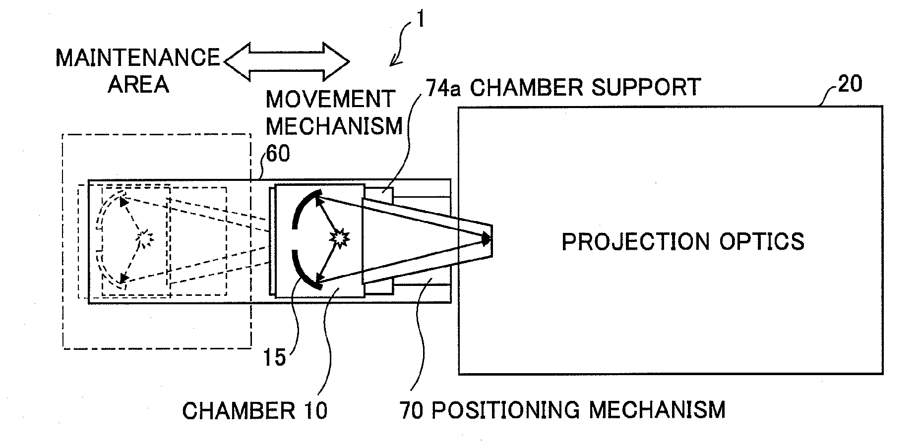
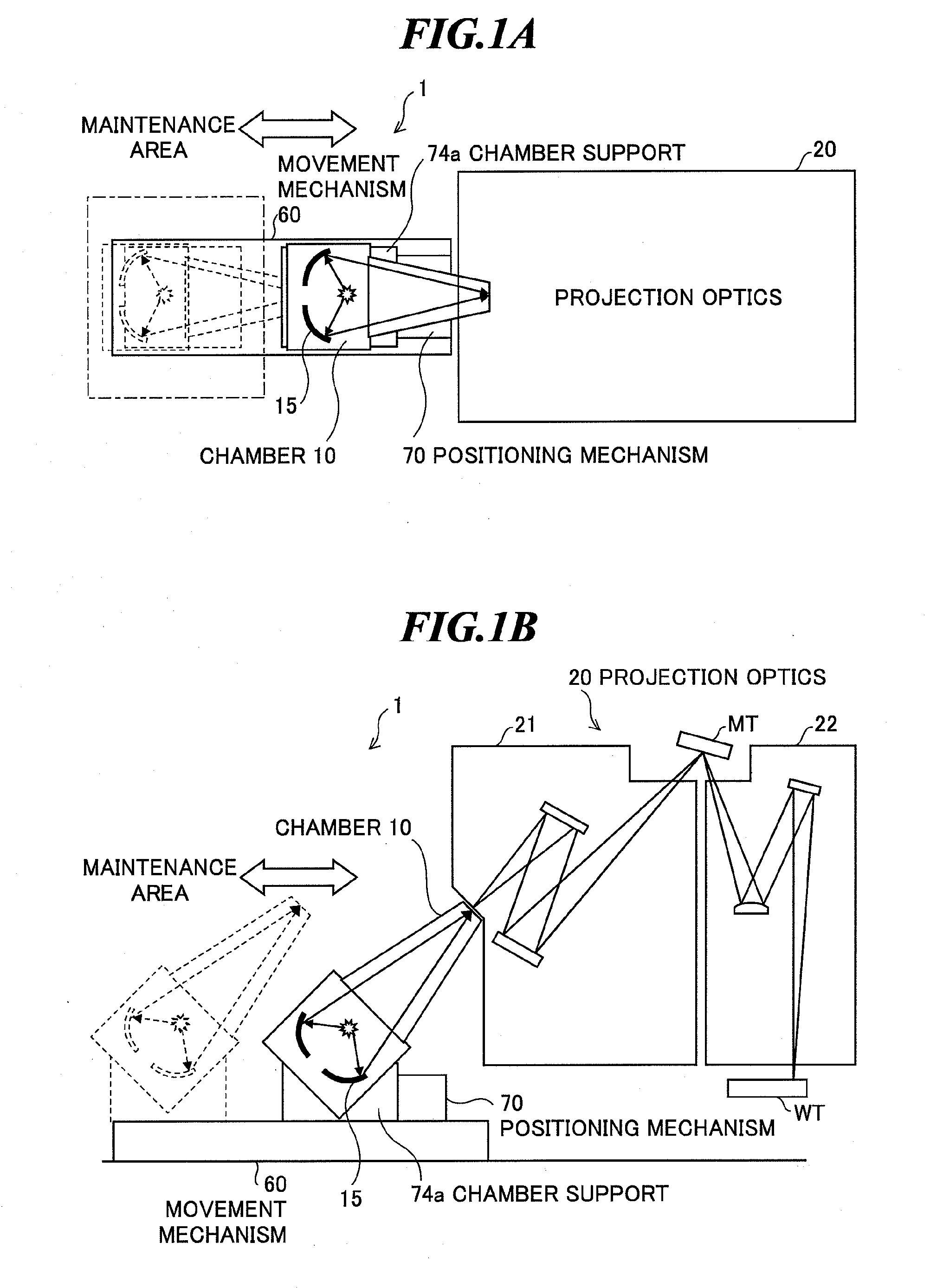
[0049]FIGS. 1A and 1B are a plan view and a side view showing an overall configuration of exposure equipment including an extreme ultraviolet (EUV) light source apparatus according to one embodiment of the invention. The exposure equipment includes an EUV light source apparatus 1 and projection optics 20.

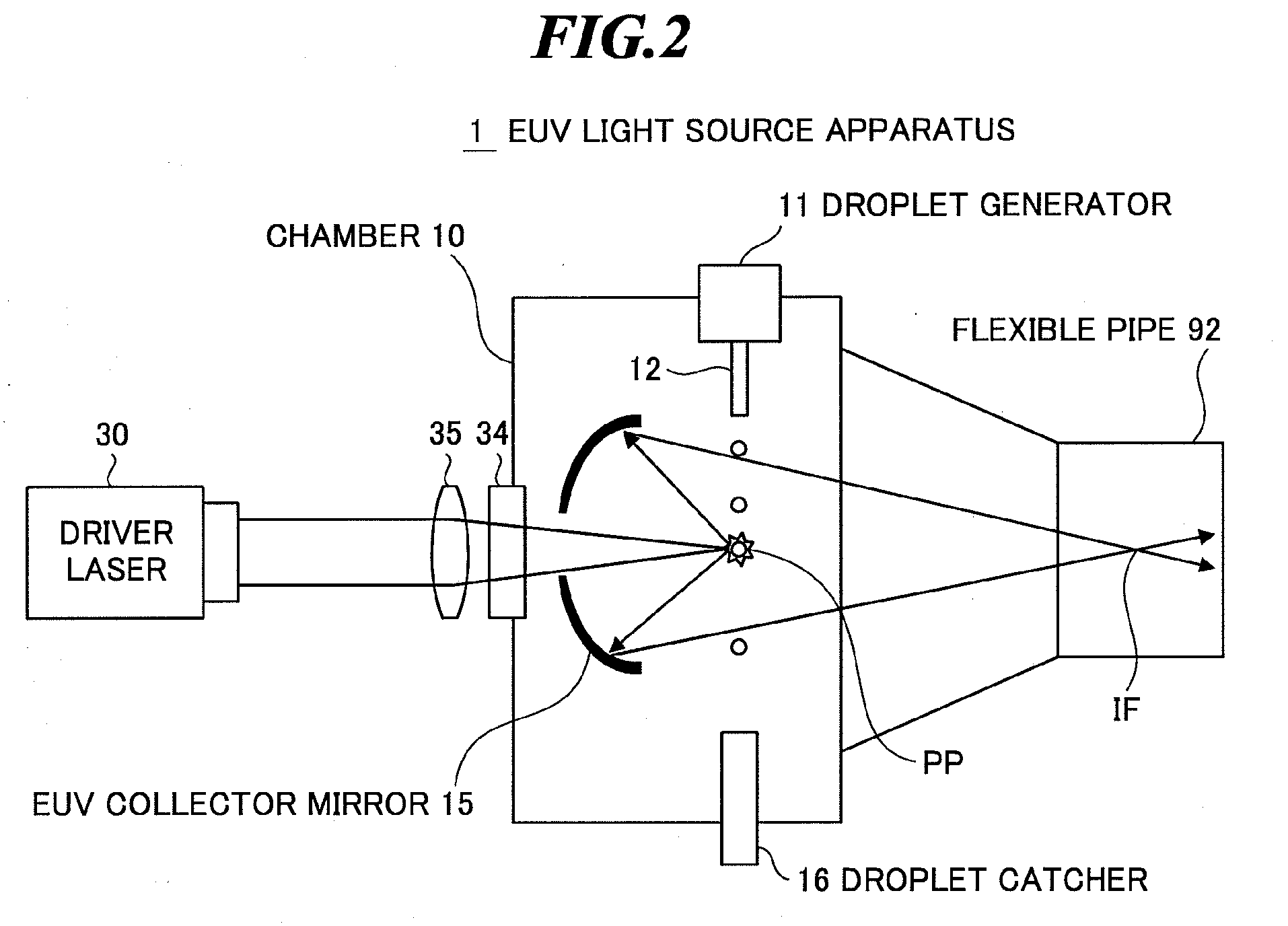
[0050]The EUV light source apparatus 1 employs a laser produced plasma (LPP) system for generating EUV light by applying a laser beam to a target material for excitation. As shown in FIGS. 1A and 1B, the EUV light source apparatus 1 has a chamber 10 in which EUV light is generated, a movement mechanism 60, and a positioning mechanism 70. The chamber 10 is a vacuum chamber in which extreme ultraviolet light is generated.

[0051]FIG. 2 is a schematic ...


PUM


Abstract

An EUV light source apparatus by which detachment of a chamber or a part of the chamber, movement to a maintenance area, and highly accurate placement relative to projection optics can be performed easily for maintenance of the EUV light source apparatus. The EUV light source apparatus is an apparatus for generating plasma by applying a laser beam to a target material within a chamber and entering EUV light radiated from the plasma into projection optics of exposure equipment, and includes a positioning mechanism for positioning the chamber or a maintenance unit of the chamber in a predetermined location where an optical axis of the collected extreme ultraviolet light and an optical axis of the projection optics of the exposure equipment are aligned, and a movement mechanism for moving the chamber or the maintenance unit of the chamber between the predetermined location and a maintenance area.

Description

CROSS-REFERENCE TO RELATED APPLICATION[0001]The present application claims priority from Japanese Patent Application No. 2008-220892 filed on Aug. 29, 2008, the contents of which are incorporated herein by reference in their entirety.BACKGROUND OF THE INVENTION[0002]1. Field of the Invention[0003]The present invention relates to an extreme ultraviolet (EUV) light source apparatus to be used as a light source of exposure equipment.[0004]2. Description of a Related Art[0005]In recent years, as semiconductor processes become finer, photolithography has been making rapid progress toward finer fabrication. In the next generation, microfabrication at 70 nm to 45 nm, further, microfabrication at 32 nm and beyond will be required. Accordingly, in order to fulfill the requirement for microfabrication at 32 nm and beyond, for example, exposure equipment is expected to be developed by combining an EUV light source for generating EUV light having a wavelength of about 13 nm and reduced projecti...

Claims


Application Information

Patent Timeline
IPC IPC(8): G21K5/04
CPCG03F7/70975G03F7/70033H05G2/00H05G2/003H05G2/008
Inventor NISHISAKA, TOSHIHIROWATANABE, YUKIOWAKABAYASHI, OSAMUKAKIZAKI, KOUJISHINOZAKI, MICHIO
Owner GIGAPHOTON
Why Eureka
Try Eureka