Refractive index distribution measuring method, refractive index distribution measuring apparatus and method of producing optical element
a technology of refractive index and measuring apparatus, which is applied in the field of refractive index distribution measuring method and refractive index distribution measuring apparatus of producing optical elements, can solve the problems of unfavorable accurate measurement of the placement of objects, unfavorable measurement of refractive index, and inability to achieve desired optical characteristics. to achieve the effect of accurately calculating the refractive index distribution of objects
- Summary
- Abstract
- Description
- Claims
- Application Information
AI Technical Summary
Benefits of technology
Problems solved by technology
Method used
Image
Examples
embodiment 1
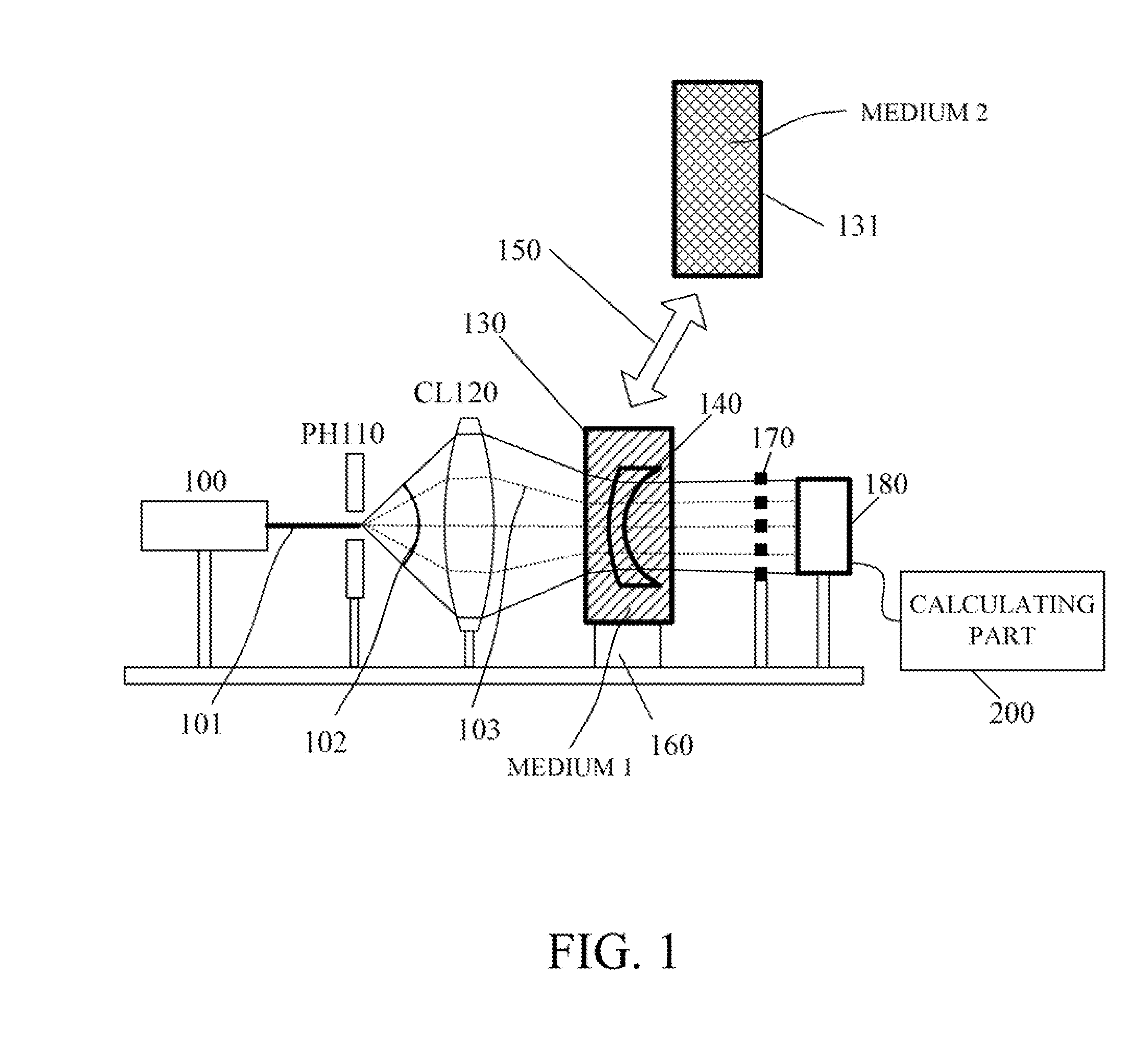
[0023]FIG. 1 shows the configuration of a refractive index measuring apparatus that is a first embodiment (Embodiment 1) of the present invention. This refractive index measuring apparatus measures (calculates) an internal refractive index distribution (hereinafter also simply referred to as “a refractive index distribution”) of an object 140 that is an optical element such as a lens.
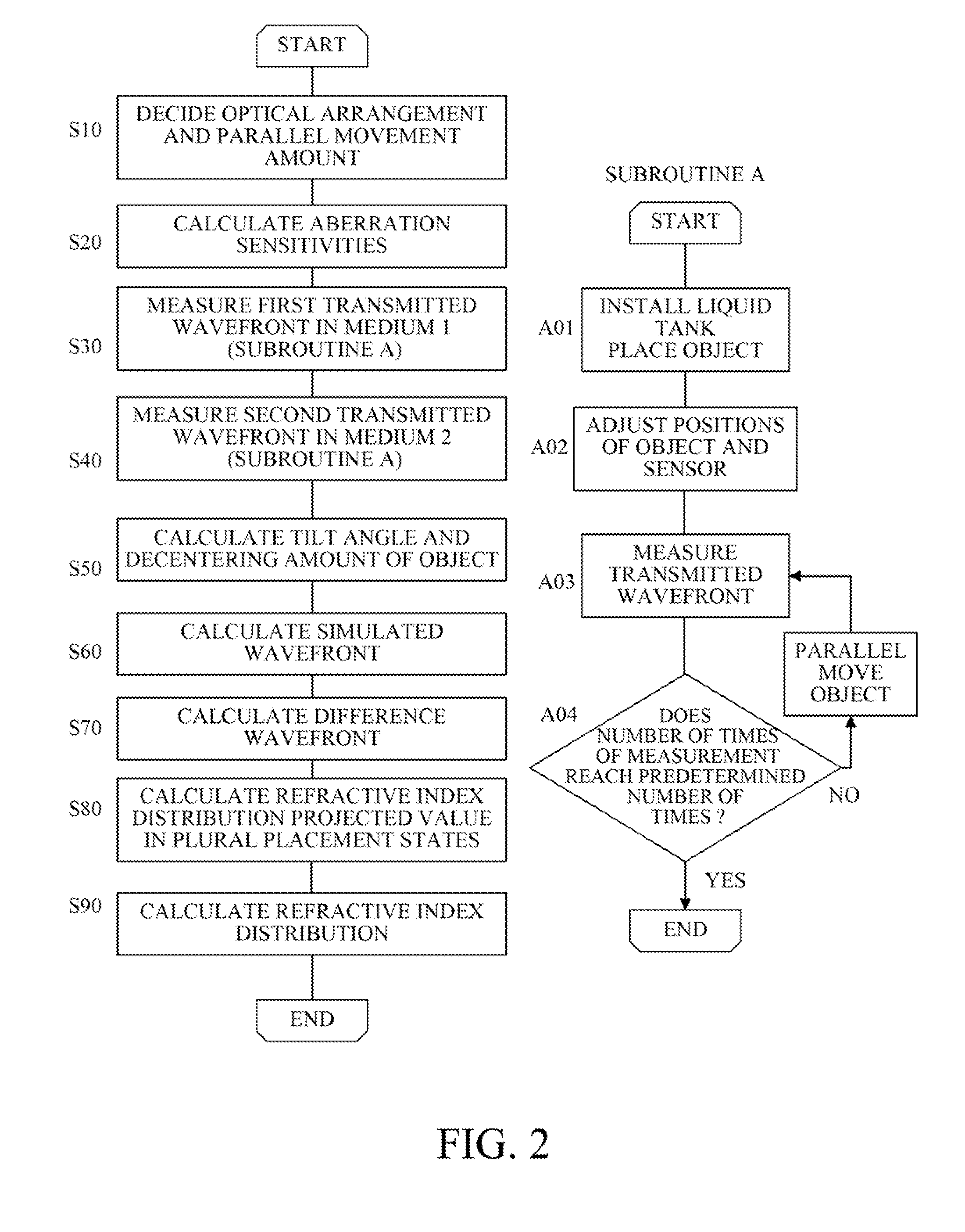
[0024]The apparatus causes reference light emitted from a laser light source 100 to enter the object 140 in states where the object 140 is soaked in two media (a first medium such as water and a second medium such as oil) having refractive indices different from each other and from that of the object, to measure a transmitted wavefront of the object 140. Then, a calculating part 200 constituted by a computer calculates the refractive index distribution of the object 140 by using the measured transmitted wavefronts. This embodiment uses a Talbot interferometer as a wavefront sensor to measure the transmi...
embodiment 2
[0092]Description will hereinafter be made of a refractive index distribution measuring apparatus that is a second embodiment (Embodiment 2) of the present invention with reference to FIG. 4. Although Embodiment 1 performs the measurement of the transmitted wavefronts in the states where the object is placed in the two media having mutually different refractive indices, Embodiment 2 performs measurement of transmitted wavefronts in states where an object is placed in a same medium, but two light sources (first reference light and second reference light) having mutually different wavelengths are used.
[0093]A refractive index distribution measuring apparatus shown in FIG. 4 uses a light source 1 (first light source) that is a He—Ne laser (wavelength 633 nm) and a light source 2 (second light source) that emits a second harmonic (wavelength 532 nm) of a YAG laser. The medium in which the object 140 is placed may be, though detailed description will be made below, a medium having a refr...
embodiment 3
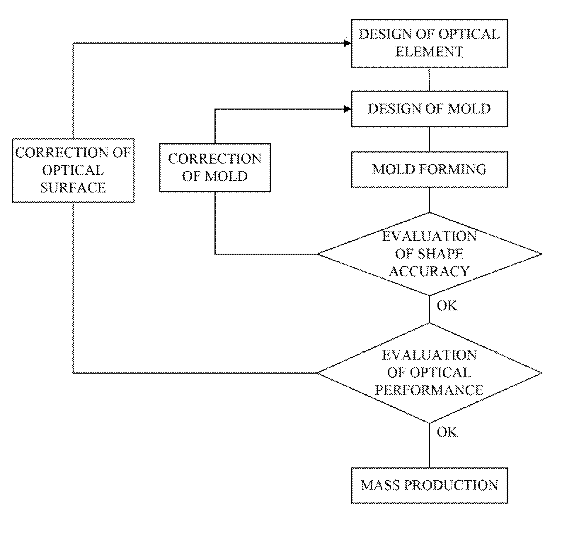
[0117]It is possible to feed back the measurement result of the refractive index distribution acquired by the measuring apparatus (or the measuring method) of each of Embodiments 1 and 2 to a method for producing optical elements such as lenses. FIG. 7 shows an example of the method for producing the optical element using mold forming.
[0118]The optical element is produced through a process of designing the optical element, a process of designing a mold and a mold forming process of forming the optical element by using the mold. The formed optical element is evaluated for shape accuracy. If the shape accuracy is deficient, the mold is corrected and then the mold forming process is performed again. If the shape accuracy is sufficient, the optical element is evaluated for optical performance.
[0119]Incorporating the refractive index distribution measuring procedure described using FIGS. 2 and 6 in this optical performance evaluating process enables mass production of the optical element...
PUM
| Property | Measurement | Unit |
|---|---|---|
| refractive index distribution | aaaaa | aaaaa |
| refractive index distribution | aaaaa | aaaaa |
| refractive index | aaaaa | aaaaa |
Abstract
Description
Claims
Application Information
 - R&D
- Intellectual Property
- Life Sciences
- Materials
- Tech Scout
- Unparalleled Data Quality
- Higher Quality Content
- 60% Fewer Hallucinations
Browse by: Latest US Patents, China's latest patents, Technical Efficacy Thesaurus, Application Domain, Technology Topic, Popular Technical Reports.
© 2025 PatSnap. All rights reserved.Legal|Privacy policy|Modern Slavery Act Transparency Statement|Sitemap|About US| Contact US: help@patsnap.com


