In-situ performance prediction of pad conditioning disk by closed loop torque monitoring

Active Publication Date: 2010-02-11
APPLIED MATERIALS INC
View PDF18 Cites 46 Cited by
  • Summary
  • Abstract
  • Description
  • Claims
  • Application Information

AI Technical Summary

Benefits of technology

[0007]In order to control the rate of material removal, the system must predict the rate of material removal. The rate of material removal from the polishing pad can be influenced by the sharpness of the abrasive surface of the conditioning disk, the compressive force, the rate of rotation and the sweep rate. The abrasive surface is made from a plurality of sharp cutting edges formed by many diamonds. As the conditioning disk is used, the sharp edges are worn down and the friction between the polishing pad is reduced. In one embodiment, the cumulative effect of these operating conditions may be measured by the rotational torque applied to the conditioning disk and the sweep torque applied to the conditioning disk arm. A rotational torque sensor can be coupled to the conditioning disk to detect the rotational torque of the conditioning disk and a sweep torque sensor can be coupled to the arm to detect the sweep torque used to move the conditioning disk across the polishing pad. A closed-loop control system controller can receive data concerning the rotational torque and the sweep torque applied to the conditioning disk and the controller makes adjustments to controllable operating conditions to maintain the rate of material removal from the conditioning disk at a constant rate to optimize the life of the polishing pad.
[0008]When the conditioning disk is new, the abrasive surface can be sharp and the amount of friction between the conditioning disk abrasive surface and the polishing pad can be large. Because of this large amount of friction, the magnitude of the detected rotational torque or the magnitude of the sweep torque may exceed the target range for a preferred rate of material removal. In order to reduce the torque, the control system can decrease the compressive force, rate of rotation and / or sweep rate applied to the conditioning disk. As the conditioning pad abrasive surface is worn down, the amount of friction between the conditioning disk abrasive surface and the polishing pad decreases and the controller must increase the compressive force, rate of rotation and / or sweep rate of the conditioning disk to bring the magnitude of the rotational torque back up to the pre-defined range. Thus, based upon data concerning the rotational torque and the sweep torque, the closed-loop control system can control the rotation torque and sweep torque applied to the conditioning disk so that the rate of material removal from the polishing pad surface is optimized for longer useful life. By controlling the rate of material removal, the change in polishing pad thickness can be substantially the same for each wafer processed. Thus, for the inventive CMP system, the change in polishing pad thickness can be directly correlated to the number of wafers processed.
[0010]The controller can operate in many different ways. For example, as described in one embodiment above, the controller can receive data concerning the magnitude of the rotational torque applied to the conditioning disk and / or the magnitude of the sweep torque applied to the arm, and controller can determine if the detected torques are within a pre-defined range of values. The rate of material removal from the polishing pad surface correlates with the rotational torque and the sweep torque. Thus, each torque value will have an associated rate of material removal. If the magnitude of the detected torques are outside the pre-defined ranges, the closed loop control system can adjust the controllable operating conditions during wafer processing to optimize the rotational and sweep torques within pre-defined ranges. Thus, the rate of material removal from the polishing pad surface is controlled to provide long life.

Problems solved by technology

If excess material is removed from the polishing pad during the conditioning process, the extra material that is removed shortens the life of the polishing pad.
Conversely, if an insufficient amount of material is removed from the polishing surface, the polishing surface will not be properly conditioned, i.e., un-desired particles may remain and the pads nominal surface characteristics may not be returned and, as a result, the wafers may not be properly polished.

Method used


Image

  • In-situ performance prediction of pad conditioning disk by closed loop torque monitoring
  • In-situ performance prediction of pad conditioning disk by closed loop torque monitoring
  • In-situ performance prediction of pad conditioning disk by closed loop torque monitoring

Examples


Embodiment Construction

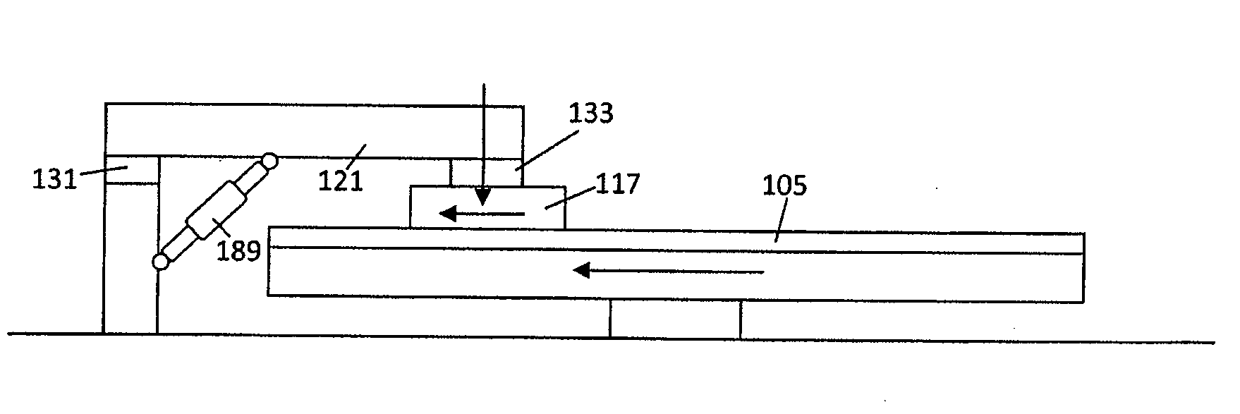
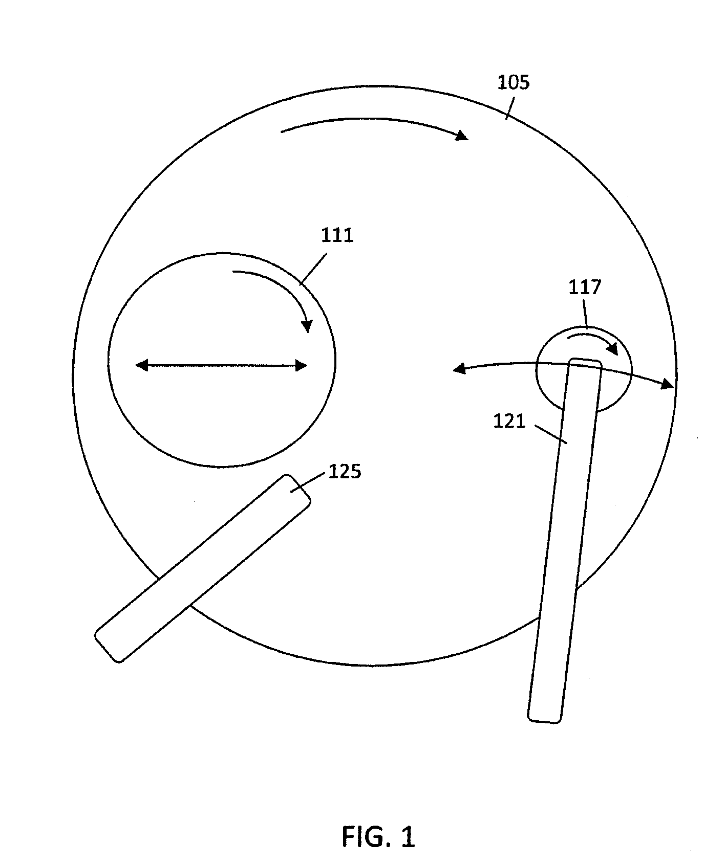
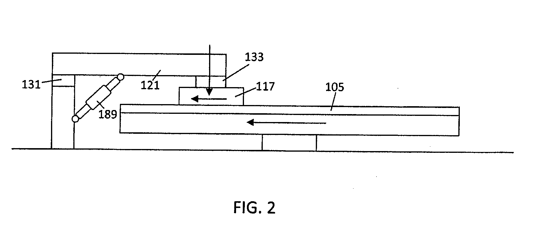
[0017]The present invention is directed towards an improved apparatus and method for optimizing the processing life of a CMP polishing pad. The inventive system detects the magnitude of the torque forces applied to the conditioning disk to condition the polishing pad and adjusts the operation of the conditioning disk to optimize the performance and life of the polishing pad. With reference to FIG. 1, a preferred embodiment of the CMP system includes a rotating circular polishing pad 105, a wafer carrier mechanism 111, a conditioning disk 117 and a conditioning disk arm. During CMP processing, abrasive slurry is poured onto the polishing pad 105 by a slurry distribution mechanism 125. The wafer carrier mechanism 111 rotates and moves the wafer over the slurry and across the width of the rotating polishing pad 105. The conditioning disk 117 has an abrasive surface that contacts the polishing pad 105 and removes wafer particles from the polishing surface. The conditioning disk 117 is s...


PUM

PropertyMeasurementUnit
Timeaaaaaaaaaa
Forceaaaaaaaaaa
Torqueaaaaaaaaaa

Abstract

Polishing pads used in CMP machines are consumable components that are typically replaced after a specific number of wafers have been processed. The life of a polishing pad is optimized by controlling the rate of material removal from the polishing pad by the conditioning disk. The conditioning disk removes enough material so the polishing surface can properly process the wafers but does not remove any excess material. Preventing excess material removal extends the life of the polishing pad. During CMP processing, the controller receives data concerning the torque applied to the conditioning disk and the torque applied to the arm to sweep the conditioning disk across the polishing pad. Based upon the detected operating conditions, the system can predict the rate of material removal and adjust the forces applied to the conditioning disk so that the life of the polishing pad is optimized.

Description

FIELD OF INVENTION[0001]The present invention relates to a method and apparatus for conditioning a polishing pad used in chemical mechanical polishing (CMP) to manufacture semiconductor devices.BACKGROUND[0002]A conventional CMP machine includes a rotating polishing pad, a wafer carrier and a conditioning disk with an abrasive surface used to condition the polishing pad. During CMP processing, a liquid slurry of abrasive particles is poured onto the rotating polishing pad and a semiconductor wafer is placed in the wafer carrier. The wafer carrier presses the wafer against the slurry and the rotating polishing pad while the carrier moves the wafer across the width of the polishing pad. The chemical reaction with the slurry and the physical erosion due to the contact with the abrasive particles causes material to be removed from the wafer and evens out any irregular topography, making the exposed wafer surface planar. The conditioning disk includes an abrasive surface and is coupled t...

Claims


Application Information

Patent Timeline
IPC IPC(8): B24B53/02
CPCB24B37/005B24B53/017B24B49/18B24B49/16H01L21/304
Inventor DESHPANDE, SAMEERCHANG, SHOU-SUNGCHEN, HUNG CHIHNANGOY, ROY C.TSAI, STAN D.
Owner APPLIED MATERIALS INC
Why Eureka
Try Eureka