
Via density change to improve wafer surface planarity

a technology of density and wafers, applied in the direction of instruments, computing, total factory control, etc., can solve the problems of poor critical dimension (cd) control, poor focus, and more subject to scumming, and achieve the effect of improving the planarity of the wafer surfa

Inactive Publication Date: 2010-02-04
GLOBALFOUNDRIES INC
View PDF9 Cites 3 Cited by
  • Summary
  • Abstract
  • Description
  • Claims
  • Application Information

AI Technical Summary

Benefits of technology

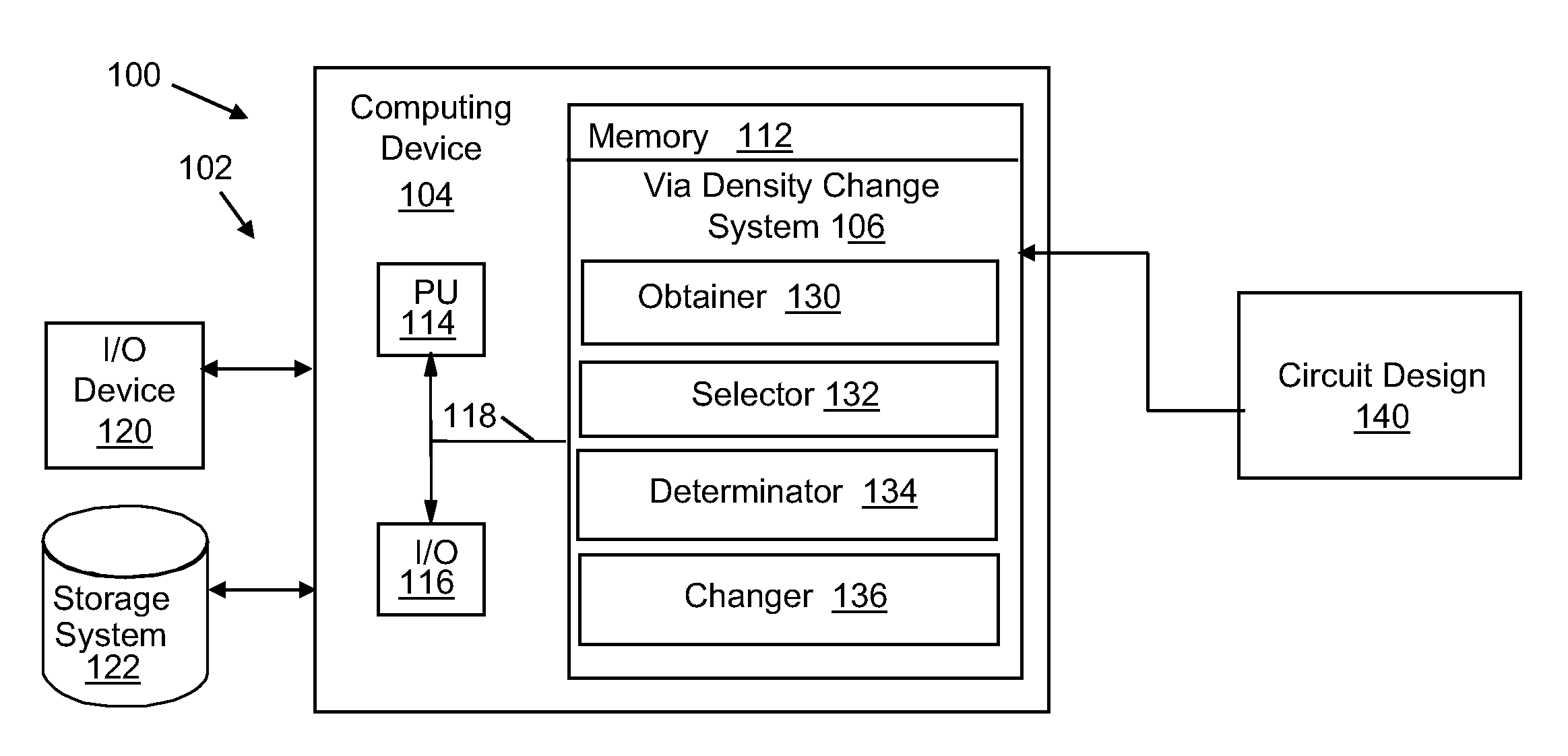
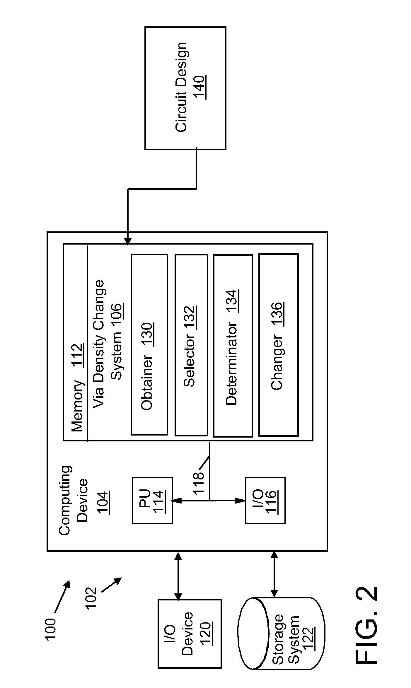
[0006]Changing a via density for viafill vias within a circuit design to improve wafer surface planarity for later photolithography is provided, in one embodiment, by obtaining a circuit design including a plurality of viafill vias having differing via density across the circuit design, each viafill via interconnecting non-functional metal fill shapes in different layers of the circuit design; selecting a region of the circuit design to evaluate using an evaluation window; determining a via density within the evaluation window; and changing a number of viafill vias within the region in the circuit design in response to the via density being different than a threshold via density that is selected such that a coating deposited over the plurality of vias presents a substantially planar surface.

Problems solved by technology

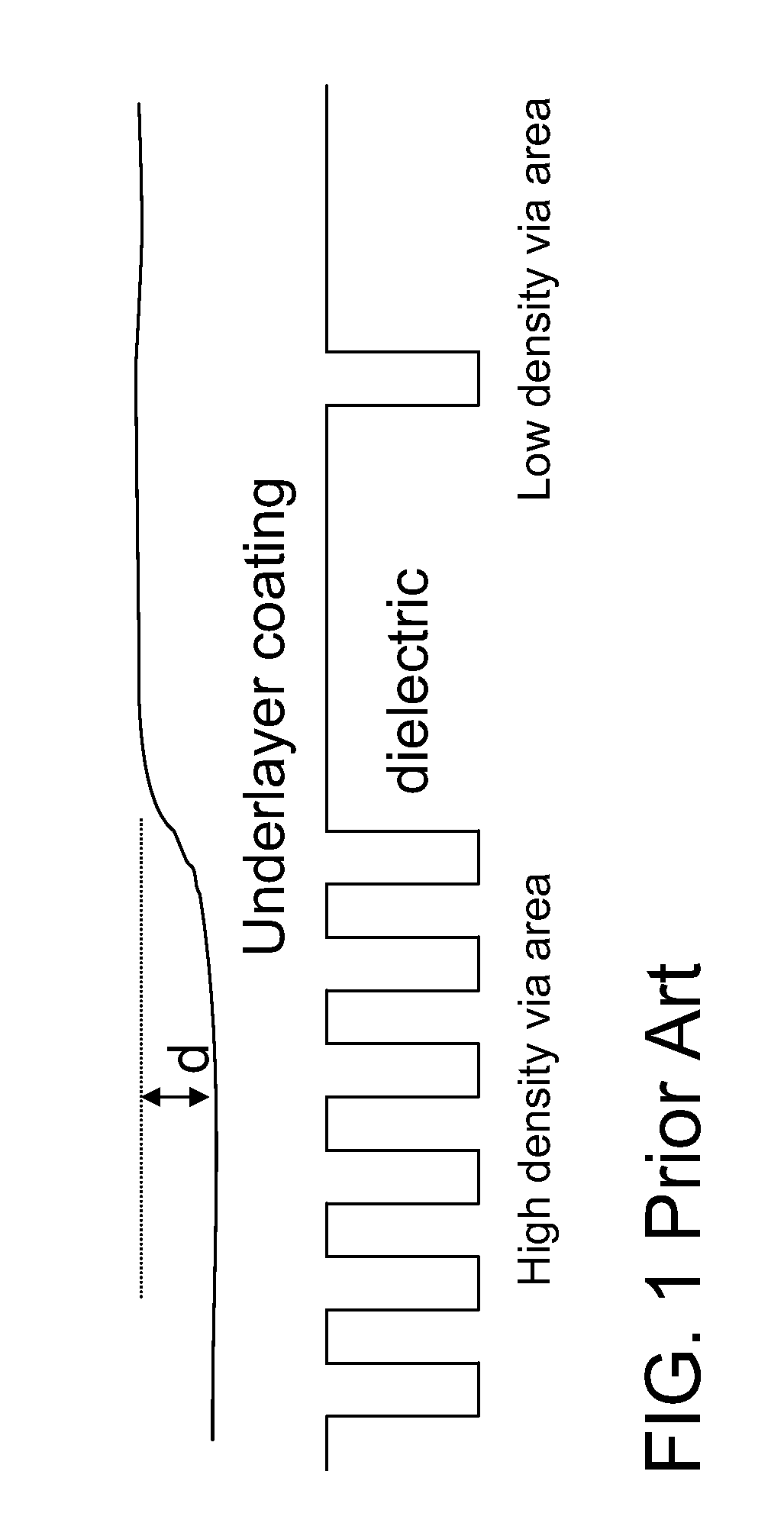
If, for instance, the majority of the slit area has a high density of vias, the line images over the low via density areas will be in particularly poor focus (other things being equal) and therefore will be more subject to scumming, poor critical dimension (CD) control and associated yield problems.
Other effects, such as non-planarity due to chemical mechanical polish (CMP), and lithography tool control factors (lens distortions, chuck imperfections, etc.) also consume portions of the available depth of focus.

Method used


Image

  • Via density change to improve wafer surface planarity
  • Via density change to improve wafer surface planarity
  • Via density change to improve wafer surface planarity

Examples


Embodiment Construction

[0017]As indicated above, the disclosure provides changing of via density for viafill vias within a circuit design to improve wafer surface planarity for later photolithography. In this manner, line level lithography processes over the via level may be presented with a more planar surface, thus allowing an increased process window. As will be appreciated by one skilled in the art, the present disclosure may be embodied as a system, method or computer program product. Accordingly, the present disclosure may take the form of an entirely hardware embodiment, an entirely software embodiment (including firmware, resident software, micro-code, etc.) or an embodiment combining software and hardware aspects that may all generally be referred to herein as a “circuit,”“module” or “system.” Furthermore, the present disclosure may take the form of a computer program product embodied in any tangible medium of expression having computer-usable program code embodied in the medium.

[0018]Any combina...


PUM


Abstract

Changing a via density for viafill vias to improve wafer surface planarity for later photolithography is provided, in one embodiment, by obtaining a circuit design including a plurality of viafill vias having differing via density across the circuit design, each viafill via interconnecting non-functional metal fill shapes in different layers of the circuit design; selecting a region of the circuit design to evaluate using an evaluation window; determining a via density within the evaluation window; and changing a number of viafill vias within the region in the circuit design in response to the via density being different than a threshold via density that is selected such that a coating deposited over the plurality of vias presents a substantially planar surface.

Description

BACKGROUND[0001]1. Technical Field[0002]The disclosure relates generally to integrated circuit (IC) chip design and fabrication, and more particularly, to changing of via density to improve wafer surface planarity.[0003]2. Background Art[0004]Fabrication of copper interconnects in today's integrated circuits usually involves “via first” dual damascene. Vias are first etched into a dielectric or dielectric stack, usually down to an etch stop layer. After resist strip, the line level processing is done, which first involves spin coating an underlayer material which fills the via holes, “planarizing” the surface. Subsequent layers are then deposited or spin coated, and line level lithography is then done. However, the degree to which the underlayer planarizes the wafer surface has been found to depend on the via density. As shown in FIG. 1, high via density areas “consume” more of the underlayer to fill the holes and this results in a wafer surface which, after underlayer coating, has ...

Claims


Application Information

Patent Timeline
Patent Type & Authority Applications(United States)
IPC IPC(8): G06F17/50
CPCG06F2217/12G06F17/5068G06F30/39G06F2119/18Y02P90/02
Inventor GRECO, STEPHEN E.
Owner GLOBALFOUNDRIES INC
Learn More