
Passive heat sink and light emitting diode lighting device using the same

a technology of light emitting diodes and heat sinks, which is applied in the direction of lighting, heating apparatus, and semiconductor/solid-state device details, etc., can solve the problems of increased manufacturing costs, increased heat accumulation, and increased temperature, so as to achieve low manufacturing costs of heat sink modules

Active Publication Date: 2010-01-28
ADVANCED OPTOELECTRONICS TECH
View PDF10 Cites 18 Cited by
  • Summary
  • Abstract
  • Description
  • Claims
  • Application Information

AI Technical Summary

Benefits of technology

[0012]The objective of the present invention is to provide a passive heat sink module and a light emitting diode lighting device using the same. The heat sink fin of the heat sink module is thinner so that the manufacturing cost of the heat sink module is low.
[0020]Because the heat sink fins of the heat sink module of the present invention are manufactured first, and subsequently soldered to the base of the heat sink module, each heat sink fin can be made as thin as possible. Moreover, when a manufacturer produces heat sink fins of different sizes or shapes, the manufacturer can use the original manufacturing tools to produce another set of heat sink fins and then solder them to the base. No new die or mold is required so that manufacturing cost can be effectively reduced.

Problems solved by technology

If generated heat is not efficiently dissipated, the accumulated heat may quickly increase the temperature of the light emitting diodes and its surrounding environment.
High temperature may have detrimental effects on the light emitting diodes.
If larger heat sink fins are desired, a new extrusion die must be prepared, and the manufacturing cost is increased.
In addition, the required thickness of the heat sink fins limits the heat dissipation area of the heat sink module.
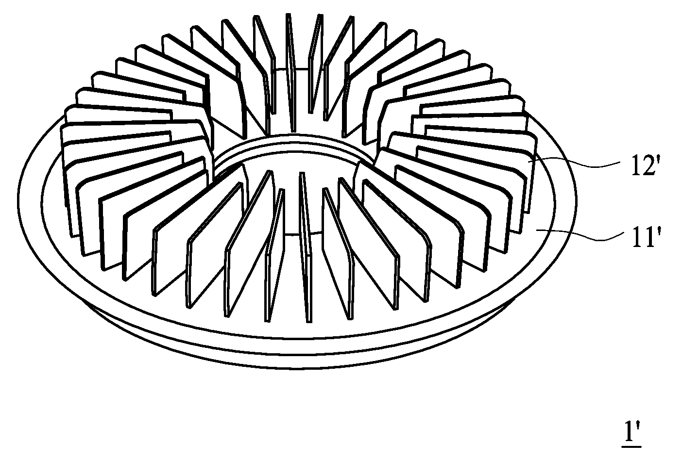
Consequently, if the heat sink fins 12 must be of at least a minimum thickness, the material cost is increased and the heat dissipation area of the heat sink module is limited.
In addition, if heat sink modules 1′ with more or fewer heat sink fins 12′ is to be produced, a new molding die must be prepared, and the manufacturing cost is increased.

Method used


Image

  • Passive heat sink and light emitting diode lighting device using the same
  • Passive heat sink and light emitting diode lighting device using the same
  • Passive heat sink and light emitting diode lighting device using the same

Examples


Embodiment Construction

[0031]FIG. 3 shows a light emitting diode (LED) lighting device according to one embodiment of the present invention. The light emitting diode lighting device 2 comprises an LED light bar 21 and a passive heat sink module 22. The LED light bar 21 includes a plurality of light emitting diodes 211 and an aluminum base plate 212, on which the plurality of the light emitting diodes 211 is disposed. The aluminum base plate 212 can be one type of metal core printed circuit board with an aluminum sheet having better heat transfer capability for increasing heat dissipation.

[0032]Compared to an active heat sink module requiring electrical power to drive a fan for dissipating heat, the passive heat sink module 22 is a heat sink module that needs no electrical power and does not include a fan. In the present embodiment, the passive heat sink module 22 includes a base 221 and a plurality of heat sink fins 222, which is disposed on the base 221 at a uniform interval. The base 221 and the heat si...


PUM


Abstract

A light emitting diode (LED) lighting device is provided. The LED lighting device includes an LED light bar and a passive heat sink. The passive heat sink includes a base and a plurality of heat sink fins. The LED light bar is placed on one side of the base, and the heat sink fins are placed on the other side of the base. The fins are fixed on the base by soldering.

Description

BACKGROUND OF THE INVENTION[0001]1. Field of the Invention[0002]The present invention relates to a heat sink module and a lighting device, and relates more particularly to a type of heat sink fin and a light emitting diode lighting device using the same.[0003]2. Description of the Related Art[0004]Light emitting diodes (hereinafter “LED”) were initially used only in indicator lights of electronic devices, and now are increasingly applied to the backlights of liquid crystal display devices, and even further to electrical illumination devices or public displays such as vehicle lighting apparatuses, traffic lights, electronic sign boards, large video walls or the illumination devices in projectors. Their range of applications continues to expand.[0005]While light emitting diodes are emitting light, heat is generated, and LEDs producing higher luminous intensities generate greater levels of heat. If generated heat is not efficiently dissipated, the accumulated heat may quickly increase ...

Claims


Application Information

Patent Timeline
Patent Type & Authority Applications(United States)
IPC IPC(8): F21V29/00
CPCF21K9/00F21S48/328F21V29/004F21Y2101/02G02F2001/133628F21V29/773H01L2924/0002H01L23/3672F21V29/763F21V29/713H01L2924/00F21Y2115/10G02F1/133628F21V29/74
Inventor TENG, YEN CHUCHANG, CHIA CHEN
Owner ADVANCED OPTOELECTRONICS TECH
Learn More