
Green ecological zero energy consumption integration house

An integrated house, zero-energy-consumption technology, applied in the direction of renewable energy integration, solar thermal power generation, energy-saving heating/cooling, etc., can solve the problems of unreachable residential buildings, waste of heating systems, and high maintenance costs

Inactive Publication Date: 2009-06-17
赵民忠
View PDF3 Cites 18 Cited by
  • Summary
  • Abstract
  • Description
  • Claims
  • Application Information

AI Technical Summary

Problems solved by technology

[0003] The invention provides a green ecological zero-energy-consumption integrated house, which solves the technical problems that the existing residential houses cannot meet the requirements of comfort, greenness and environmental protection, the heating system wastes energy seriously, and the maintenance cost is high

Method used


Image

  • Green ecological zero energy consumption integration house
  • Green ecological zero energy consumption integration house
  • Green ecological zero energy consumption integration house

Examples


Embodiment 1

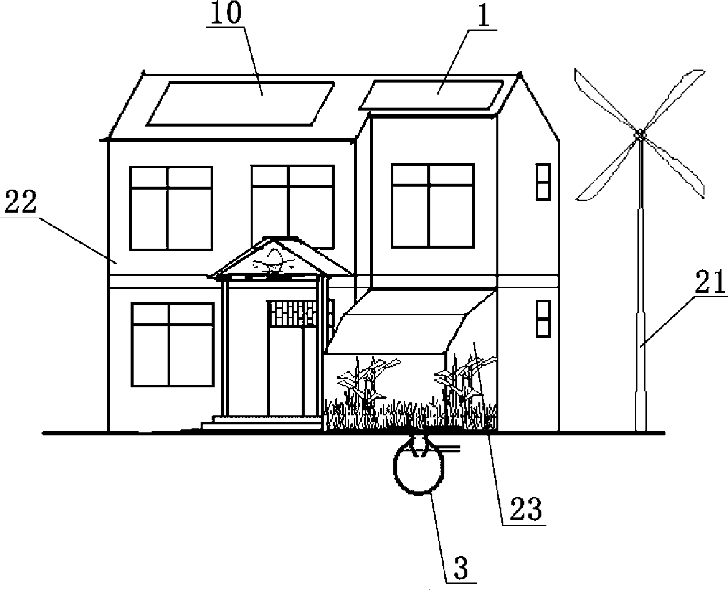
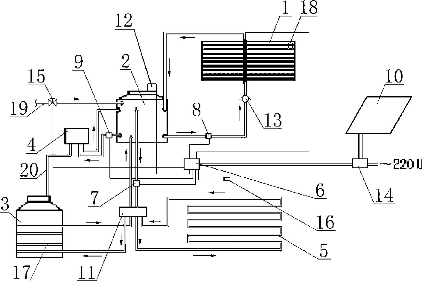
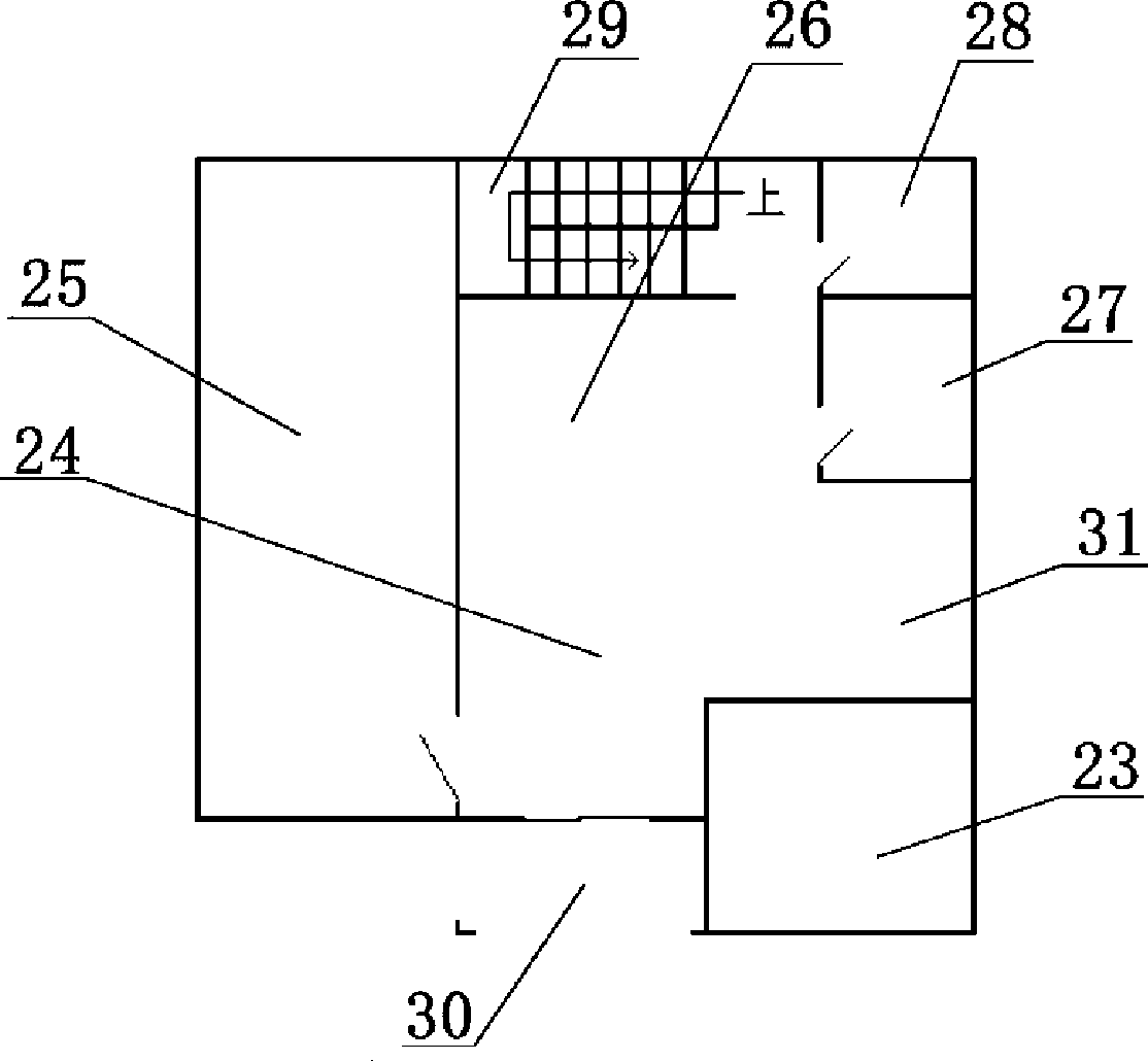
[0043]Embodiment one sees Figure 1-4 As shown, this green ecological zero-energy integrated house has two floors. The doors and windows of the above-mentioned building 22 are double-layer hollow glass doors and windows. The building is equipped with a heating system, the ground of the building 22 is connected with the solar greenhouse 23, and the underground is connected with the biogas pit 3, and the water inlet pipe of the biogas pit 3 is connected with the sewage pipe 33 in the bathroom. The solar heat collector 1 located on the top of the building communicates with the thermal insulation water tank 2 located in the building room through a circulating water pipe, and the thermal insulation water tank 2 communicates with the cold water inlet pipe 19 through the solenoid valve 15, and leads from the thermal insulation water tank 2 to the solar heat collector. The circulating water pipe of device 1 is connected with solar collector circulation pump 8 and check valve 13.

[0...

Embodiment 2

[0050] Embodiment two see Figure 5 As shown, there is also a reclaimed water treatment system 46 in the hospital of the present invention, and the reclaimed water treatment system is connected with the biogas digester 3 and connected with the water supply equipment in the kitchen and the toilet.

[0051] see Figure 6 , the thin-shell thermal insulation composite wallboard 45 adopted by the building is composed of an outer shell and an inner filling core, and the outer shell is connected by a thin-walled panel 34 made of inorganic glass fiber reinforced plastic and a thin-walled inner partition 35 to form a distributed The whole of the lattice-shaped cavity, the filling core is a light-weight micro-bubble solid insulation material filled in the above-mentioned cavity. The above-mentioned lightweight microfoam solid insulation material can be extruded polystyrene board 36 or magnesite foamed concrete 37 . The connecting surfaces on both sides of the above shell are flat open...


PUM


Abstract

The invention relates to a green ecological zero energy integrated building, a first floor of the building is provided with a living room, a bedroom, a dinning room, a kitchen, a toilet; a second floor of the building is provided with a bedroom and a toilet; a heat supply system is arranged inside the room, the building is connected with a heliogreenhouse on the ground and is connected with a methane tank under the ground. A solar thermal collector arranged at the top of the building is communicated with a temperature-holder box arranged inside the rooms of the building by a circulating pipe of the first line, the temperature-holder box is communicated with a water heating pipe of a gas-fuel heater by the circulating pipe, a gas line of the gas-fuel heater is communicated with the methane tank by a methane pipe. A hot water outlet of the temperature-holder box is respectively communicated with a PE-RT pipe and a heating pipe of the methane tank which is buried near the methane tank. A water tank temperature sensor, a room temperature sensor and a collector temperature sensor are connected with an intelligent controller. With the solar energy, bioenergy and wind energy complementing each other, the building has the characteristics of comfort, environmental protection, energy saving and zero-pollution.

Description

technical field [0001] The invention relates to a residential house. Background technique [0002] With the improvement of people's living standards, people's requirements for quality of life and living environment are also constantly improving. my country's villa construction is gradually developing towards comfort, green and environmental protection. The high energy consumption of buildings mainly depends on the thermal insulation performance of the building. However, the current villa buildings generally have the problems of high heating and cooling costs, poor thermal insulation and energy-saving performance, dry and cold in winter, and hot in summer, which cannot meet the requirements of comfort, greenness and environmental protection. Known solar heat collectors and circulating water pipes thereof are generally used to supply domestic hot water, and its heat is not enough to supply heating systems. Known biogas and gas heater systems are generally used in cooking sys...

Claims


Application Information

Patent Timeline
Patent Type & Authority Applications(China)
IPC IPC(8): E04H1/04F24D15/02F24J2/04E04B2/72
CPCY02B30/12Y02E10/44Y02B10/20
Inventor 赵民忠
Owner 赵民忠
Learn More