
Lightweight and compact subsea intervention package and method

a subsea and package technology, applied in the direction of sealing/packing, drilling pipes, borehole/well accessories, etc., can solve the problems of significant fluid leakage, prior art systems may be slow to operate to perform these functions, and subsea wells do not perform at/to the same level of performance, etc., to improve the handling capability of the riser system and reduce weight

Inactive Publication Date: 2010-01-21
WORLDWIDE OILFIELD MACHINE INC
View PDF64 Cites 16 Cited by
  • Summary
  • Abstract
  • Description
  • Claims
  • Application Information

AI Technical Summary

Benefits of technology

[0013]Another objective of the present invention is to provide a light weight intervention package for use with 7⅜ inch bore and operable for severing 2⅞ inch coiled tubing if necessary and / or severing production tubing with 0.204 wall thickness and / or reliably and repeatably cutting tubulars of at least 2¾″ or more, if desired, without the need for maintenance.
[0015]Accordingly, the present invention comprises a lightweight subsea intervention package for use in servicing a subsea well. The subsea well may comprise at least one of a vertical Christmas tree or a horizontal Christmas tree. The subsea intervention package may preferably be operable for containing the subsea well even while using at least one of tubing, pipe, rods, coiled tubing, or wireline, which may need to be cut in an emergency, during the servicing of the subsea wells. The subsea intervention package may comprise one or more elements such as, for example only, a lower package attachable to the subsea well regardless of whether the subsea well comprises the vertical Christmas tree or the horizontal Christmas tree. The lower package may further comprise at least two hydraulically actuated valves wherein preferably neither of which are B.O.P.'s. At least one of the at least two hydraulically actuated valves may preferably be operable cutting the tubing, coiled tubing, wireline, and / or other members, and then closing to form a seal for sealing the subsea well. In one possible embodiment, the lower package may define a bore through the two hydraulically actuated valves which is greater than seven inches. In a preferred embodiment, the lightweight subsea intervention package may be light enough and define a footprint small enough such that the lightweight subsea intervention package can be installed on the subsea well utilizing a vessel with a handling capacity less than that of a semi-submersible platform.
[0024]In one embodiment for use with a riser, the method may further comprise providing an integral swivel and flow head for the riser to permit a vessel supporting the riser to weather around the riser. The integral swivel and flowhead also provides a surprisingly improved handling capability of the riser system by the support vessel, rig, or other means utilized to control the subsea well intervention.
[0025]The method may further comprise providing that at least one hydraulically actuated valve comprises a fail-safe actuator which is mounted on one side of a valve body and a manual override actuator mounted on an opposite side of the valve body. This arrangement reduces weight and prevents members from extending outside the designated dimensions while providing a large borehole. Additionally, the method may further comprise mounting an independent supply of hydraulic fluid on the subsea intervention package and providing that at least one hydraulically actuated valve comprises an actuator mounted on one side of the at least one hydraulically actuated valve operable to utilize the independent supply of hydraulic fluid.

Problems solved by technology

Often subsea wells do not perform at / to the same levels of performance as platform wells mainly due to the high costs of servicing subsea wells, which may be referred to herein as subsea well interventions.
Prior art systems may be slow to operate to perform these functions and may sometimes allow significant amounts of fluid leakage before isolation is accomplished.
A small increase in the size of the tree plug often results in a significant increase in the size of the intervention package.
This system is very heavy and bulky.
Accordingly, the time to move the platform to location and set the anchors is rather long.
The overall cost of the intervention operation utilizing a subsea drilling BOP intervention system is quite high but the system provides the means for doing any type of desired work.
Other attempts to produce lightweight systems have limitations that make them unsuitable for some types of intervention work.

Method used


Image

  • Lightweight and compact subsea intervention package and method
  • Lightweight and compact subsea intervention package and method
  • Lightweight and compact subsea intervention package and method

Examples


Embodiment Construction

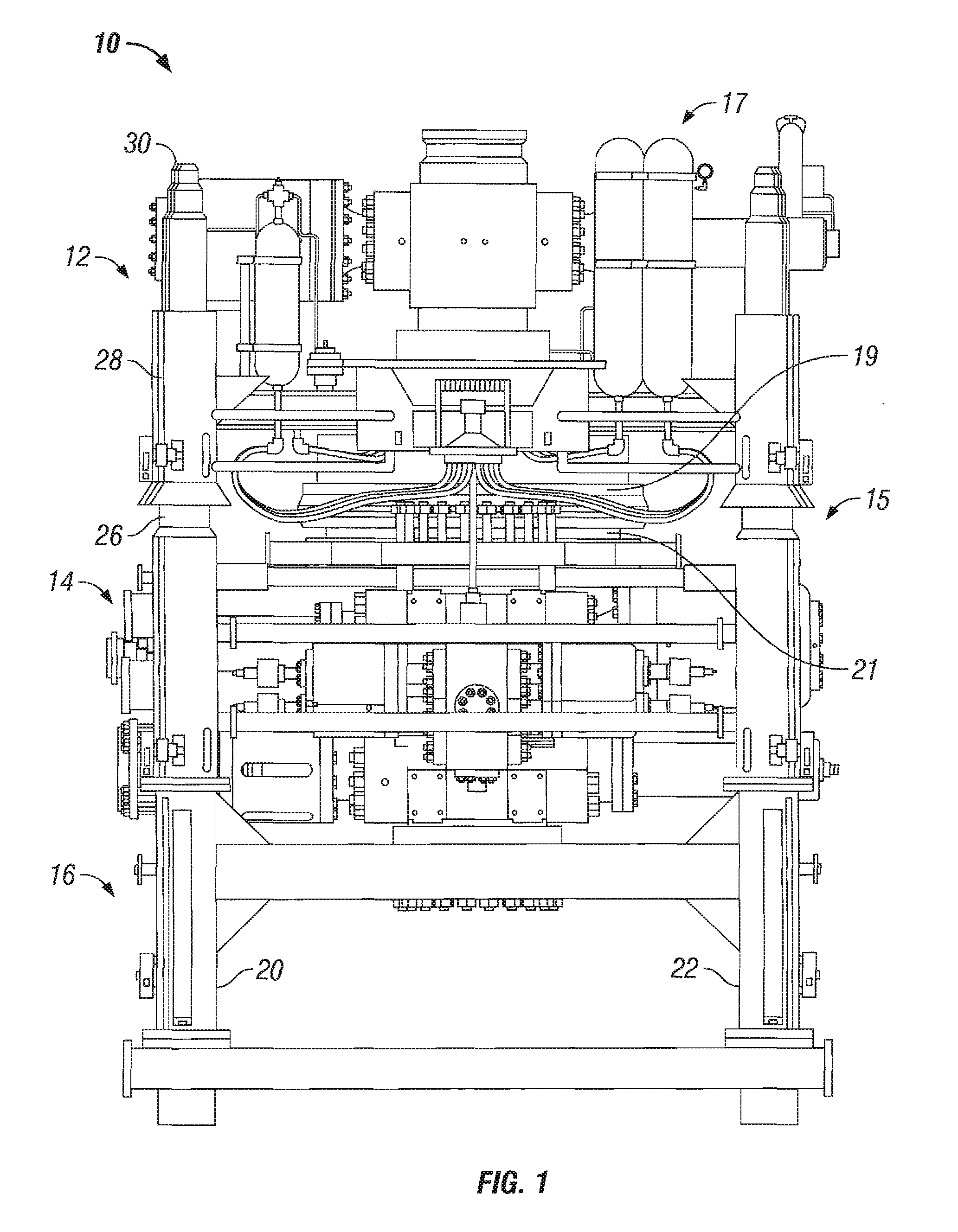
[0039]Referring now to the drawings, and more particularly to the figure, there is shown one embodiment of a lightweight, compact, subsea intervention package 10, in accord with the present invention. Due to the physical space limitations surrounding the wellbore, such as equipment already in place around the subsea wellbore, it is desirable that subsea intervention package 10 be as compact as possible with little or no extensions outside of the frame. The absence of components jutting substantially outside the boundaries of the subsea intervention package also makes subsea intervention package 10 much easier to handle and deploy.

[0040]In one preferred embodiment of the present invention, subsea intervention package 10 may be utilized in either a riser mode or a subsea wireline mode and / or a subsea coiled tubing mode, as discussed in more detail hereinafter. Subsea intervention package 10 is modular to permit changing from one mode of operation to another with minimum time and effor...


PUM


Abstract

The present invention discloses apparatus and methods for a lightweight subsea intervention package that may be installed using vessels with a smaller lifting capacity than semi-submersible platforms so that the subsea intervention package can be transported, installed, and removed from a subsea well in less time and with less cost. In one embodiment, the present invention comprises a lower riser package for controlling the subsea well which utilizes two hydraulically activated gate valves. An emergency disconnect package is secured to the lower riser package utilizing a disconnect mechanism. The emergency disconnect package is operable to seal the bottom of a riser if the disconnect mechanism is activated to thereby minimize environmental leakage of fluid from the riser.

Description

[0001]This application is a divisional application of U.S. patent application Ser. No. 10 / 532,358, filed Apr. 20, 2005, which is incorporated herein in its entirety; U.S. patent application Ser. No. 10 / 532,358 claims benefit of U.S. Provisional Application No. 60 / 478,988 filed Jun. 17, 2003, which is incorporated herein in its entirety, and is a continuation-in-part of U.S. patent application Ser. No. 09 / 992,220 filed Nov. 6, 2001, now U.S. Pat. No. 6,601,650 B2, which is incorporated herein in its entirety, and is a continuation-in-part of U.S. patent application Ser. No. 09 / 925,676, filed Aug. 9, 2001, now U.S. Pat. No. 6,575,426 B2, which is incorporated herein in its entirety, and is a continuation in part application of U.S. patent application Ser. No. 09 / 802,209, filed Mar. 8, 2001, now U.S. Pat. No. 6,609,533 B2, which is incorporated herein in its entirety, and is a continuation in part application of U.S. patent application Ser. No. 10 / 459,243, filed Jun. 11, 2003, now U.S....

Claims


Application Information

Patent Timeline
IPC IPC(8): E21B29/00E21B34/06
CPCE21B33/064E21B17/02E21B33/038E21B33/076E21B29/12
Inventor SUNDARARAJAN, ALAGARSAMYMCCREADIE, TOM
Owner WORLDWIDE OILFIELD MACHINE INC
Learn More