
Three-dimensional transistor with double channel configuration

a transistor and double channel technology, applied in the direction of transistors, semiconductor devices, electrical apparatus, etc., can solve the problems of less efficient devices in speed and power consumption when compared to static ram cells, more complex circuit components may be created, and the bit density of dram devices may be very high, so as to improve the controllability of the body region, the effect of scalability and enhanced functionality

Active Publication Date: 2009-12-31
GLOBALFOUNDRIES US INC
View PDF20 Cites 34 Cited by
  • Summary
  • Abstract
  • Description
  • Claims
  • Application Information

AI Technical Summary

Benefits of technology

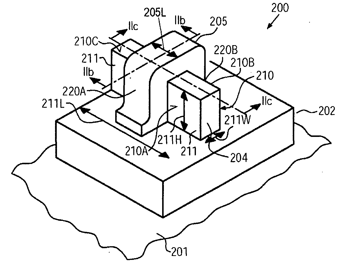
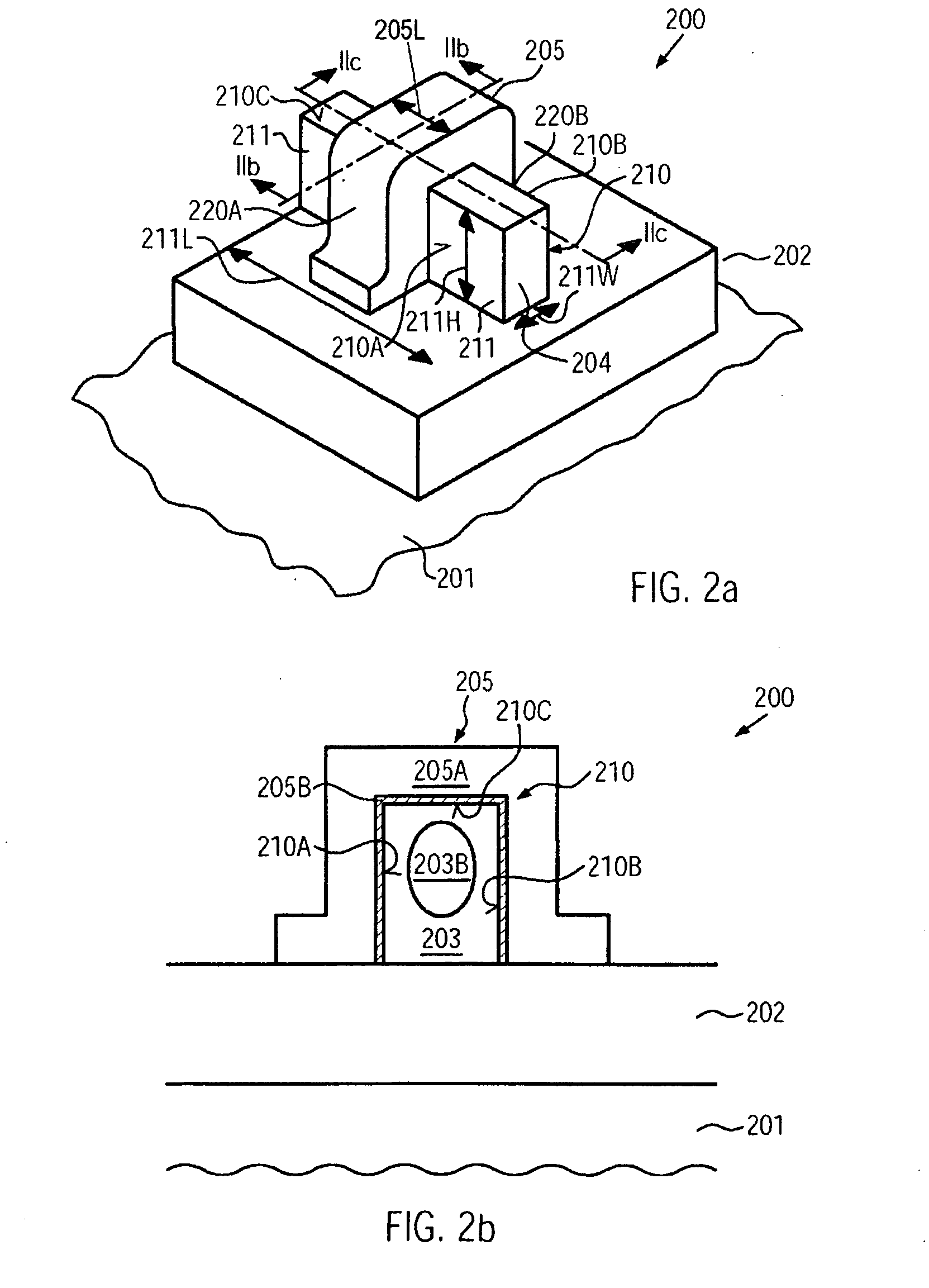
[0013]Generally, the subject matter disclosed herein relates to transistor devices having an increased functionality in combination with the potential for further scalability in that a three-dimensional transistor configuration may be provided, in which the body region of the transistor may comprise an additional doped region, thereby defining a volume within the body region that may act as a “second” channel region. Consequently, by appropriately positioning the “second” channel region within the body of a three-dimensional transistor, such as a FinFET, a tri-gate transistor, a nano wire or nano pipe field effect transistor and the like, enhanced controllability of the body region, i.e., the channel of the three-dimensional transistor architecture, is achieved, while nevertheless creating a modified trans-conductance of the transistor, which may result in a three-state behavior, as previously explained for conventional planar double channel transistor. By using a three-dimensional configuration, i.e., by providing a gate electrode structure on non-coplanar surface areas of the body region or on a curved surface, in the case of nano wire or nano pipe FET, overall controllability and current flow may be enhanced, while nevertheless the lateral dimensions of the transistors may be reduced more efficiently compared to conventional planar transistor architectures. In some illustrative aspects disclosed herein, the three-state behavior of the transistor slope may be used to form a memory cell, which may comprise a reduced number of transistor elements due to the intrinsic characteristics of the three-dimensional transistors including an additional channel volume, while also a further scalability may be provided due to the generally three-dimensional architecture.

Problems solved by technology

On the basis of field effect transistors, more complex circuit components may be created.
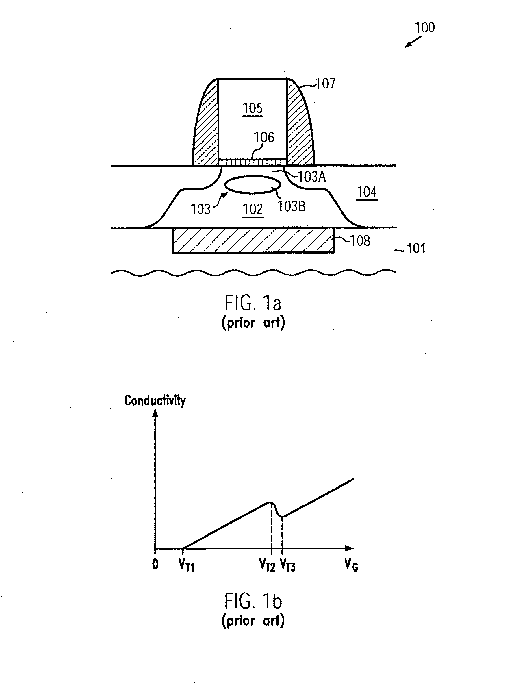
Typically, a dynamic RAM cell comprises a storage capacitor and a single transistor, wherein, however, a complex memory management system is required to periodically refresh the charge stored in the storage capacitors, which may otherwise be lost due to unavoidable leakage currents.
Although the bit density of DRAM devices may be very high, a charge has to be transferred from and to storage capacitors in combination with periodic refresh pulses, thereby rendering these devices less efficient in terms of speed and power consumption when compared to static RAM cells.
Although significant advantages may be gained with respect to increased functionality and / or reduced area consumption of basis electronic circuits, such as RAM cells, which may be provided on the basis of less than 6 planar double channel transistors, a further advance with respect to increased information density per chip unit area may be difficult to be achieved due to the limitations of appropriate control of current flow between the source and drain regions in planar transistor configurations.
In particular, for device generations with highly scaled transistor elements including gate electrode structures having a length of 30 nm and less, extremely complex manufacturing techniques may have to be applied to account for the reduced controllability of the transistor behavior.
Consequently, the provision of a second channel region may contribute to a corresponding high degree of complexity of establishing an appropriate dopant profile in planar field effect transistors having a second channel region.
Thus, in view of a further scalability of the overall device dimensions, drive current capability and / or channel controllability may be difficult to be realized according to conventional techniques, as described above.

Method used


Image

  • Three-dimensional transistor with double channel configuration
  • Three-dimensional transistor with double channel configuration
  • Three-dimensional transistor with double channel configuration

Examples


Embodiment Construction

[0029]Various illustrative embodiments of the invention are described below. In the interest of clarity, not all features of an actual implementation are described in this specification. It will of course be appreciated that in the development of any such actual embodiment, numerous implementation-specific decisions must be made to achieve the developers' specific goals, such as compliance with system-related and business-related constraints, which will vary from one implementation to another. Moreover, it will be appreciated that such a development effort might be complex and time-consuming, but would nevertheless be a routine undertaking for those of ordinary skill in the art having the benefit of this disclosure.

[0030]The present subject matter will now be described with reference to the attached figures. Various structures, systems and devices are schematically depicted in the drawings for purposes of explanation only and so as to not obscure the present disclosure with details ...


PUM


Abstract

A three-dimensional double channel transistor configuration is provided in which a second channel region may be embedded into the body region of the transistor, thereby providing a three-state behavior, which may therefore increase functionality of conventional three-dimensional transistor architectures. The double channel three-dimensional transistors may be used for forming a static RAM cell with a reduced number of transistors, while also providing scalability by taking advantage of the enhanced controllability of FinFETS and nano pipe transistor architectures.

Description

BACKGROUND OF THE INVENTION[0001]1. Field of the Invention[0002]The present disclosure generally relates to the fabrication of integrated circuits, and, more particularly, to transistor architectures that enable an extended functionality of transistor devices, thereby providing the potential for simplifying the configuration of circuit elements, such as registers, static RAM cells and the like.[0003]2. Description of the Related Art[0004]In modern integrated circuits, such as microprocessors, storage devices and the like, a great number of circuit elements, especially transistors, are provided and operated on a restricted chip area. Although immense progress has been made over the recent decades with respect to increased performance and reduced feature sizes of the circuit elements, the ongoing demand for enhanced functionality of electronic devices forces semiconductor manufacturers to steadily reduce the dimensions of the circuit elements and to increase the operating speed thereo...

Claims


Application Information

Patent Timeline
Patent Type & Authority Applications(United States)
IPC IPC(8): H01L29/78H10B10/00
CPCH01L27/11H01L27/1104H01L29/0673H01L29/78696H01L29/66795H01L29/785H01L29/42392H10B10/00H10B10/12
Inventor WIRBELEIT, FRANK
Owner GLOBALFOUNDRIES US INC
Learn More