Hydration station

Inactive Publication Date: 2009-12-17
HAWS CORP
View PDF20 Cites 24 Cited by
  • Summary
  • Abstract
  • Description
  • Claims
  • Application Information

AI Technical Summary

Benefits of technology

[0006]The unit is activated by means of an infrared sensor 46 below the nozzle 78, removing the need for any physical contact on the part of the user (see FIGS. 1 and 5). An increased signal return from the infrared sensor 46 indicates the presence of an object in the sensor path; this object must continue to trigger the sensor 46 for a very short delay period (which should allow the user to fully position his or her receptacle underneath the nozzle 78), after which a solenoid valve 35 will open (see FIG. 2), permitting water flow to the nozzle 78.
[0007]A timer feature 81 (see FIG. 10) is built into the main electronic board 68 (FIG. 9); this timer 81 resets every time the unit is used. If the timer 81 is allowed to reach twenty-four hours, the solenoid valve 35 will be activated automatically for a matter of seconds, flushing the water through the nozzle 78 and out of the system. In this manner, water is not permitted to remain in the unit for more than a 24-hour period, preventing the buildup of harmful bacteria over time.
[0009]A nozzle outlet 40 is equipped with a number of equally spaced mesh screens 41 and 42 designed to remove inherent turbulence from the water from and create a softer, more uniform flow (see FIG. 4). A nozzle housing 44 encases a small printed circuit board 45 with a number of LED lights 82 (see FIG. 11 and FIG. 12); these lights 82 normally pulse at a reduced brightness level to indicate that the electronics are functioning properly, with the produced light being externally visible in the upper region of the alcove immediately below the nozzle 78 near the top of the alcove, and generally in front of the infrared sensor 46. When the unit is activated upon operation of the infrared sensor 46 to open the solenoid valve 35 to initiate water flow, the LED lights 82 engage immediately at full brightness, both to indicate that the sensor 46 has been triggered and to further assist in the positioning of the user's receptacle beneath the nozzle 78.
[0012]When the upper panel 15 is in an open position, a large cutout 85 (FIG. 3) in the steel back panel 13 offers access to the internal plumbing and other components. In this way, a number of maintenance items can be performed quickly and easily. The service life of the filter 25 can be assessed with a flow totalizer 21 (FIGS. 2, 7 and 13), and a filter cartridge (not shown) used in the inline carbon filter 25 can be changed as needed. In addition, the open upper panel 15 allows a drain grate 53 (FIGS. 1 and 6) to be unbolted and removed so that a drain 50 and strainer 54 (FIG. 6) can be cleaned and serviced. A lower panel 14 is permanently secured or constrained to the back panel 13, providing a robust waste plumbing configuration.
[0013]In essence, the present invention therefore comprises an unobtrusive system or means for delivering purified water through a sanitized system into the user's water receptacle. The invention requires essentially no floor space, and does not utilize the large water containers typically associated with many point-of-use coolers; rather, it fits easily and securely within a wall 83. There are a number of features which are intended to minimize the spread of bacteria and foreign particulates to the user, including a carbon filter 25, antimicrobial components (40, 44, and 47), non-contact activation by means of a “hands-off” sensor 46, and the automatic purging cycle built into a main circuit board 68 (FIG. 9). Maintenance is expedited and simplified by means of the hinged upper panel 15.

Problems solved by technology

There are problems associated with both types of dispensers.
Both dispensers, for instance, usually have a substantial footprint, which can be a difficulty in offices or any areas where space is a premium commodity.
Both types of dispenser, being used by a large number of individuals and having areas that are frequently wet, have a great capacity to be unsanitary.
Drinking fountains, and some point-of-use water coolers, rely on an input of municipal water, which, depending on geography as well as the condition of the inlet plumbing, can be of inferior quality.
Many point-of-use coolers utilize purified drinking water purchased on a regular basis, which is far more expensive per gallon than municipal water.

Method used


Image

  • Hydration station
  • Hydration station
  • Hydration station

Examples


Embodiment Construction

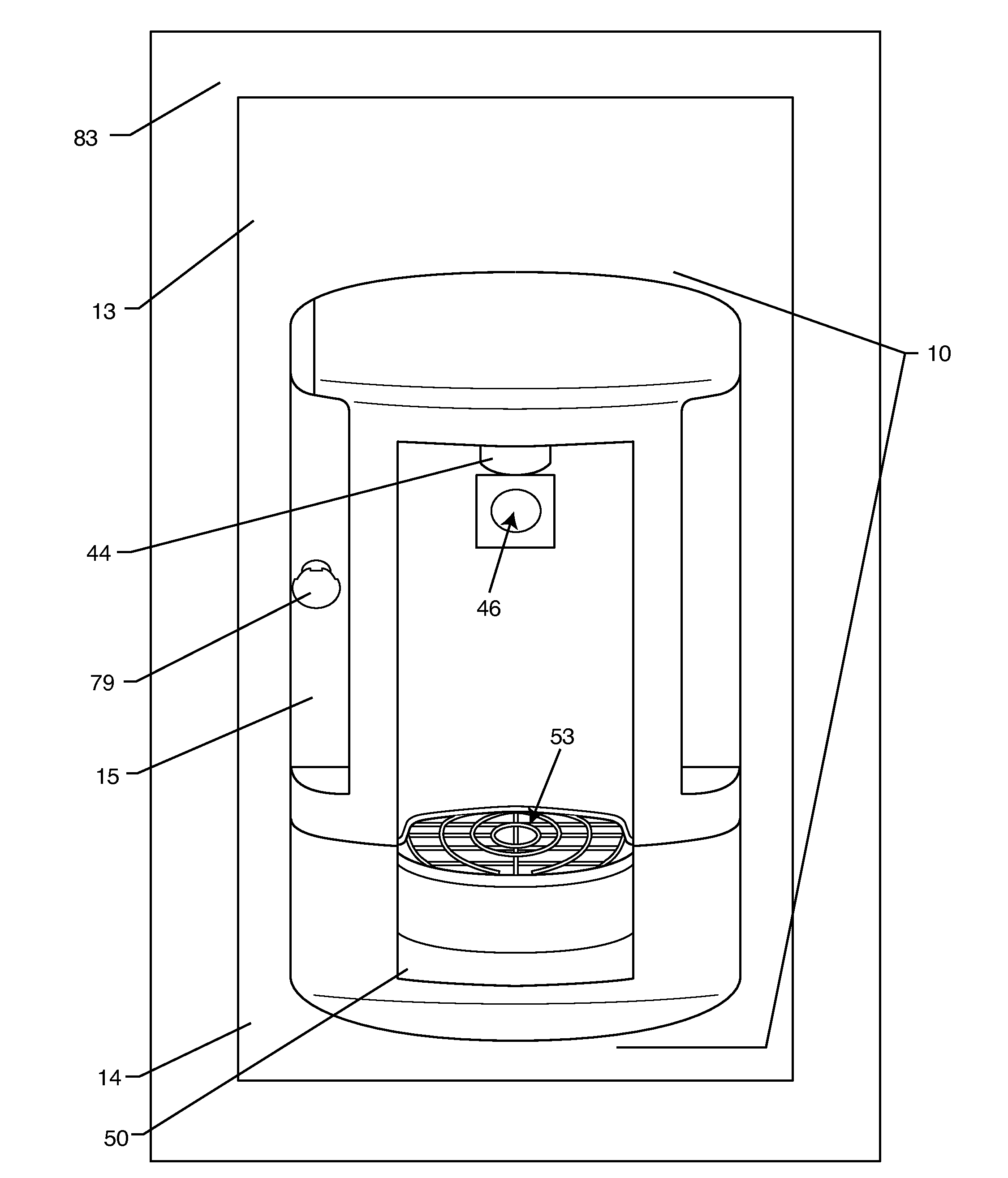
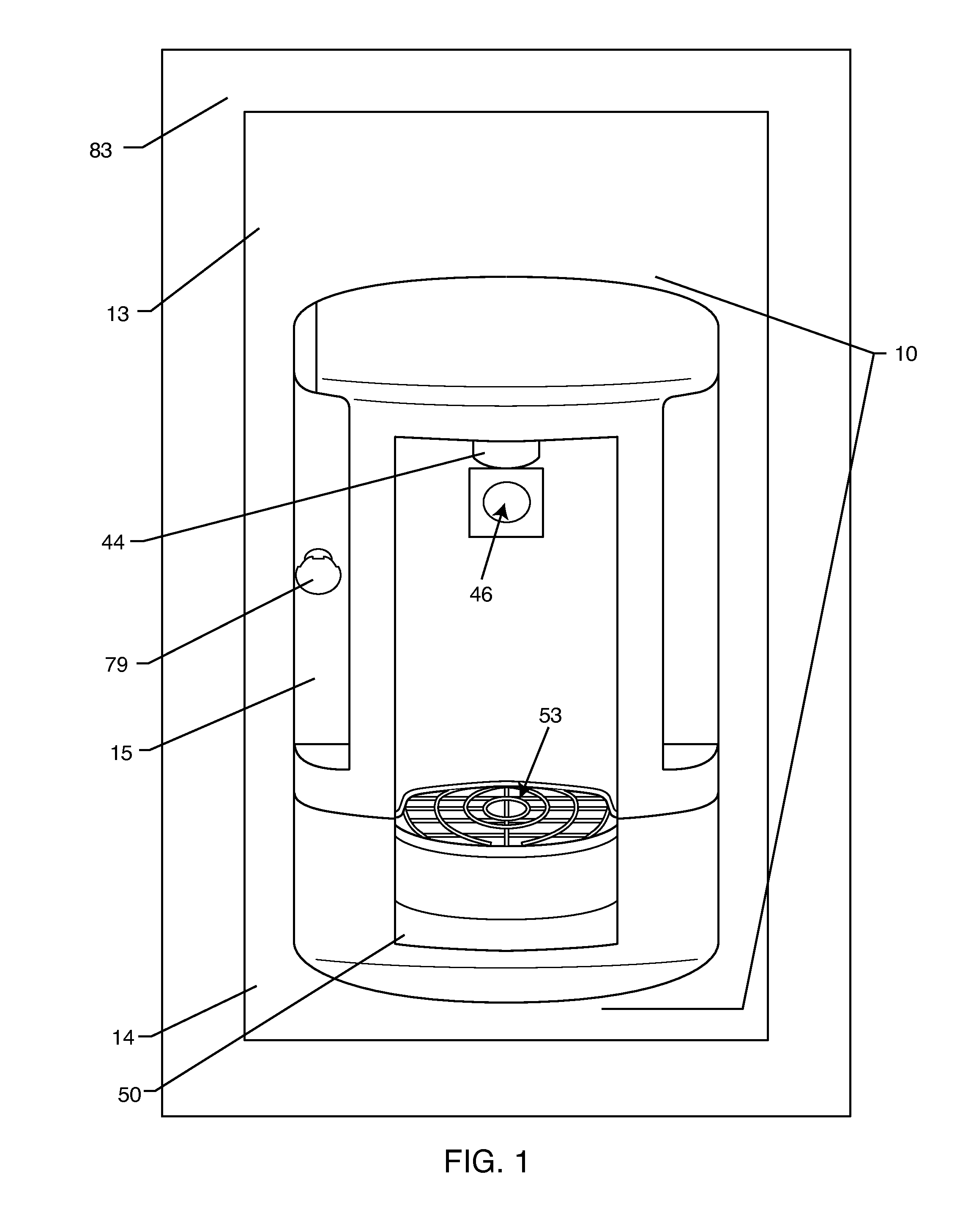
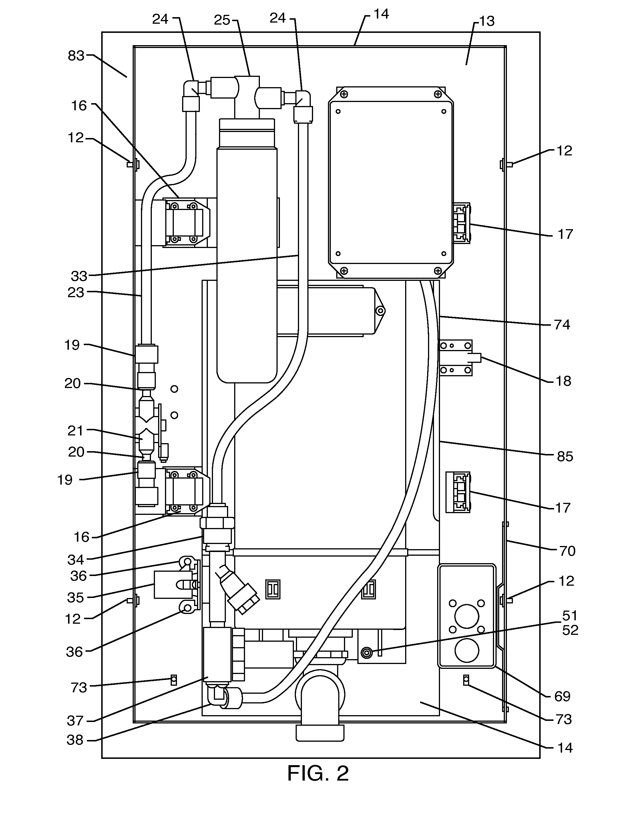
[0033]As seen in the attached drawings, an improved hydration station comprises a main water dispenser assembly (denoted by reference numeral 10) in the form of a wall-mounted unit; a rectangular mounting frame 11 is used to provide support and mounting for the device (FIGS. 2 and 3); this mounting frame 11 has a number of holes through which mounting screws may be affixed into wall studs (not shown) or similar items of a wall 83 or the like. Four panel clips 12 (FIG. 2) provide an interface between this mounting frame 11 and a sheet metal panel 13 (FIG. 1) formed from stainless steel or the like. This sheet metal panel 13 in turn butts against the wall 83 and provides central mounting for the main components of the unit 10.

[0034]The main body of the wall-mounted device or unit 10 is split into two separate contoured panels which are situated on the outboard or end-user side of the device (FIG. 1). A lower body panel 14 is a stationary piece which houses the drain and waste, while a...


PUM

PropertyMeasurementUnit
Timeaaaaaaaaaa
Timeaaaaaaaaaa
Flow rateaaaaaaaaaa

Abstract

An improved hydration station comprises a wall mounted unit including a stationary lower body panel coupled to a drain, and a hinged upper body panel carrying a nozzle subassembly for dispensing water into a recess alcove defined cooperatively by the lower and upper body panels in response to user-insertion of a water-receiving receptacle into the alcove. The preferred wall unit includes a non-contact sensor for controlling water dispensing flow, and a preferred nozzle assembly includes at least one component having an antimicrobial additive. A preferred control timer automatically dispenses water in the event that the sensor does not detect a user-inserted receptable within a predetermined time interval, such as 24 hours. In addition, in a preferred form, lights on the unit are energized at one level during water dispensing, and at a second level when water is not being dispensed.

Description

BACKGROUND OF THE INVENTION[0001]This invention relates primarily to improvements in the delivery and dispensing of drinking water, particularly to drinking water delivered in a public facility or place of work. This invention is intended to improve both the quality of the water issued and the means of delivery for this water.[0002]Two kinds of drinking water dispensers are typically used in public areas. The first is the traditional drinking fountain, which emits a stream of water at a near-vertical angle from a purpose-built bubbler head, when the user activates a valve (usually with a button or lever); the user drinks directly from this stream. Any wasted water is usually caught in the basin of the fountain and is disposed of through a plumbed drain. The second type of dispenser is a point-of-use water cooler, which is usually a free-standing floor unit with a large removable water reservoir on the top. This water, which is often replenished on a regular basis by a drinking water...

Claims


Application Information

Patent Timeline
IPC IPC(8): B65B1/04C02F1/00
CPCB67D1/0014B67D1/07B67D1/0875C02F1/283B67D1/124B67D2210/0001B67D1/0888
Inventor LINN, JOSHUA D.
Owner HAWS CORP
Why Eureka
Try Eureka