
Anode for Bioelectric Power Generation And Power Generation Method And Apparatus Utilizing Same

a bioelectric power generation and anode technology, applied in the field of bioelectric power generation, can solve the problems of low energy efficiency and complex apparatus, the diffusion rate of dissolved oxygen in water has a high possibility of becoming a rate limiting step of the entire reaction, and the diffusion rate of dissolved oxygen is found to be a limiting factor, etc., to achieve the effect of simple method, simple apparatus and efficient biological power generation

Inactive Publication Date: 2009-12-03
EBARA CORP
View PDF4 Cites 17 Cited by
  • Summary
  • Abstract
  • Description
  • Claims
  • Application Information

AI Technical Summary

Benefits of technology

The patent text describes a technology for generating power from wet-type organic substances, such as wastewater, using microorganisms. The technology involves separating the oxidation-reduction reaction of the substrate and oxygen into two steps, using anaerobic organisms to produce methane or other organic compounds, and then using the methane or other compounds as a fuel for a biological fuel cell. The technology has advantages of low energy efficiency and a simplified apparatus compared to previous methods. However, the current value per unit surface area of the electrode without stirring is at most 20 μA / cm2, and the diffusion rate of dissolved oxygen in water is a limiting factor for oxidation of the substrate. The patent text also discusses the use of electron mediators in biological fuel cell technologies, but the standard electrode potentials of the proposed electron mediators do not overlap the standard electrode potentials of the final electron acceptor for anaerobic microorganisms. The technical problem addressed by the patent is to form an effective cascade of potential among the iron oxide(III) reductase, the electron mediator, and the anode, to improve the efficiency of power generation.

Problems solved by technology

Thus, this method has the problems of low energy efficiency and a complex apparatus.
As for these methods, the cathode is installed in water, so that the diffusion rate of dissolved oxygen in water has a high possibility of becoming a rate limiting step of the entire reaction.
Hence, the diffusion rate of dissolved oxygen is found to be a limiting factor for oxidation of the wet-type organic substance and power generation.
However, the document is lacking in descriptions and embodiments showing the concrete structure of an apparatus using the air electrode.
Thus, the document fails to disclose a means for solving the problems to such an extent that one of ordinary skill in the art could put it into practice.
However, the standard electrode potentials of the electron mediators used in these methods do not overlap the standard electrode potentials of final electron acceptor for anaerobic microorganisms generally used in biological fuel cell reactions, and there is a problem of being unable to form an effective cascade of potential.
Thus, an effective cascade of potential cannot be formed among the iron oxide(III) reductase, the electron mediator and the anode.
Thus, an effective cascade of potential cannot be formed among the sulfur reductase, the electron mediator and the anode.
However, the potential difference is greater than 0.3 V, so that biological electron transfer is likely to be very difficult.
In addition, to increase power generation efficiency, it is required to cause the largest possible potential difference for the oxygen reduction reaction at the cathode, but due to the high potentials of these electron mediators, potential differences of more than 0.3 V are lost, resulting in great energy losses.
Further in the case of continuously generating power, there is a problem such that the electron mediator is discharged together with the substrate liquor out of the system when the substrate solution in the anode compartment is renewed, and the addition of the electron mediator has to be continued at all times.
This change further makes the utilization of the electron mediatorby organisms difficult.
In the case that the polymer layer shows hydrophobicity, a reduction reaction itself is difficult.
This causes the problem that the oxidation efficiency of the reduced form quinone is poor, and the overvoltage of activation also becomes high.
However, none of the methods and conditions for this requirement is disclosed.

Method used


Image

  • Anode for Bioelectric Power Generation And Power Generation Method And Apparatus Utilizing Same
  • Anode for Bioelectric Power Generation And Power Generation Method And Apparatus Utilizing Same
  • Anode for Bioelectric Power Generation And Power Generation Method And Apparatus Utilizing Same

Examples


example 2

[0174]In Example 2, an anode (2) installed in the biological power generation apparatus was prepared by the method described below. Polyethyleneimine was dissolved in water to a concentration of 10 g / L to prepare a hydrophilic polymer solution. A graphite felt as an electroconductive base material was immersed in the hydrophilic polymer solution, which was shaken for 30 seconds. Then, the graphite felt was withdrawn and, after the excess hydrophilic polymer solution was removed, the graphite felt was dried for 24 hours at 100° C. to form a hydrophilic polymer layer. An increase in the weight of the graphite felt by this operation was measured, and the thickness of the hydrophilic polymer layer was calculated from the surface area of the felt measured with a specific surface area meter, and the specific gravity 1.2 of the solidified polymer. This thickness was estimated at an average of 23 nm.

[0175]The so obtained hydrophilic polymer-coated felt (electroconductive base material) was ...

example 3

[0178]In Example 3, an anode (3) installed in the biological power generation apparatus was prepared by the method described below. Polyethyleneimine was dissolved in water to a concentration of 10 g / L to prepare a hydrophilic polymer solution. A graphite felt as an electroconductive base material was immersed in the hydrophilic polymer solution and, with gentle stirring, ethyl(3-dimethylaminopropyl)carbodiimide hydrochloride was added. The reaction was performed for 72 hours to form an amide bond between the graphite and polyethyleneimine. Then, the graphite felt was taken out from the solution, and after the excess hydrophilic polymer solution was removed, the graphite felt was dried for 24 hours at 100° C. to form a hydrophilic polymer layer. The product was washed with 0.1 mol / L of a sodium hydroxide solution, and then the procedure mentioned below was performed. The thickness of the hydrophilic polymer layer was estimated at an average of 21 nm.

[0179]The thus obtained hydrophil...

example 4

[0182]In Example 4, an anode (4) installed in the biological power generation apparatus was prepared by the method described below. Polyethyleneimine was dissolved in water to a concentration of 10 g / L to prepare a hydrophilic polymer solution. A graphite felt as an electroconductive base material was immersed in the hydrophilic polymer solution under the same conditions as in Example 2. The graphite felt was withdrawn and, after the excess hydrophilic polymer solution was removed, the graphite felt was dried for 24 hours at 100° C. to form a hydrophilic polymer layer. The thickness of the hydrophilic polymer layer was estimated at an average of 23 nm.

[0183]The thus obtained hydrophilic polymer-coated felt (electroconductive base material) was immersed in tetrahydrofuran, and the aforementioned AQS chloride was added in an amount equimolar with the constituent hydrophilic monomer units of the hydrophilic polymer. A sulfonamide bond was formed under the same conditions as in Example ...


PUM

PropertyMeasurementUnit
thicknessaaaaaaaaaa
concentrationaaaaaaaaaa
pHaaaaaaaaaa

Abstract

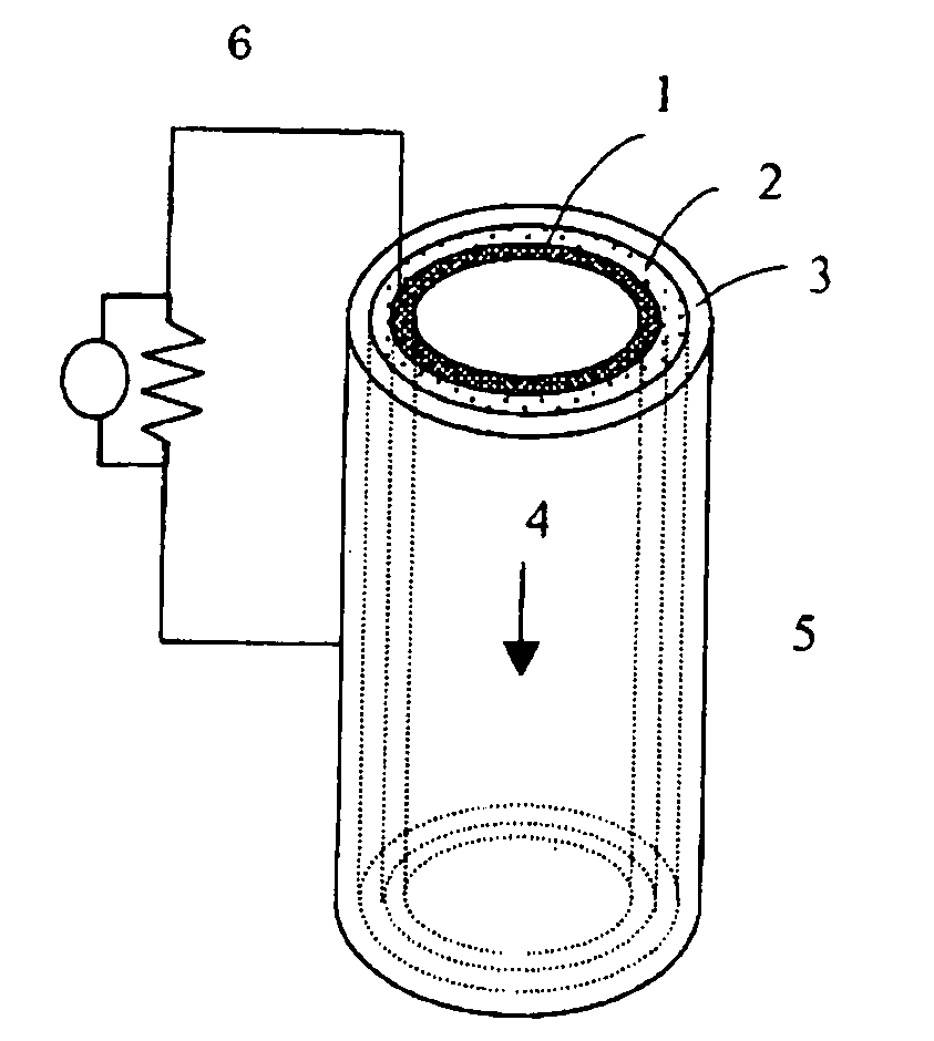
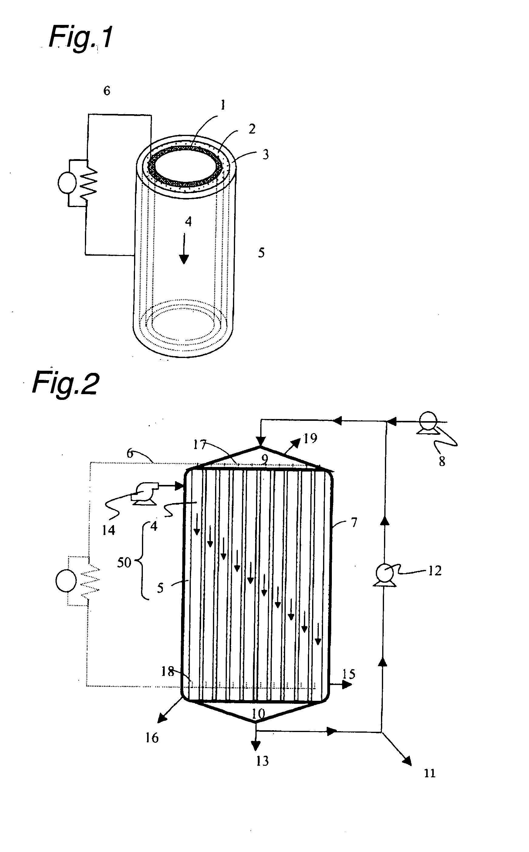
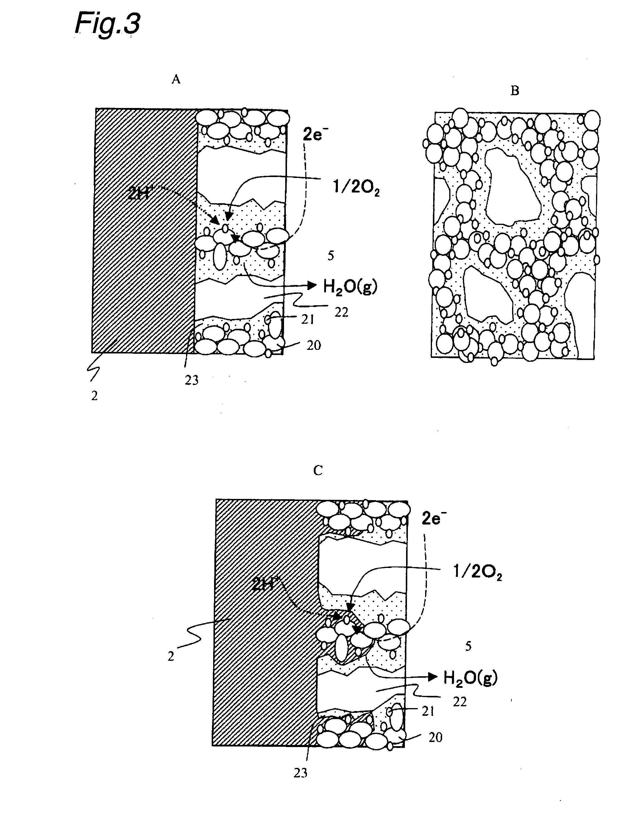
A method and a device for obtaining electric energy efficiently from a hydrous organic substance by suppressing the activation overvoltage of an anode low and thereby obtaining a sufficiently low anode potential. The power generating device comprises an anaerobic region (4) including microorganisms which can grow under anaerobic conditions, solution or suspension containing an organic substance, an electron mediator and an anode (1), an aerobic region (5) including molecular oxygen and a cathode (3), and a diaphragm (2) defining the anaerobic region (4) and the aerobic region (5), wherein a closed circuit (6) is formed by connecting the anode (1) and the cathode (3) electrically with a power utilization apparatus, and oxidation reaction of microorganisms using the organic substance in the anaerobic region (4) as electron donor and a reduction reaction using oxygen in the aerobic region (5) as electron acceptor are utilized. The anode (1) includes a conductive substrate having a surface coated at least partly with a hydrophilic polymer layer, an electron mediator is introduced into the hydrophilic polymer layer with chemical bond, and the anode (1) has a standard electrode potential (E0′) at pH 7 in a range of −0.13 V to −0.28 V.

Description

TECHNICAL FIELD[0001]This invention relates to a biological power generation technology which uses, as a substrate, an organic substance such as wastewater, liquid waste, night soil, food waste, other organic wastes, or sludge or a decomposition product thereof, and separates an oxidation-reduction reaction between the substrate and oxygen in air into an oxidation reaction by anaerobic organisms and a reduction reaction of oxygen, thereby performing power generation.BACKGROUND ART[0002]As methods for obtaining usable energy by decomposing wastewater, liquid waste, night soil, food waste, other organic waste, or sludge (hereinafter referred to as “a wet-type organic substance”), there have been worked out a method which produces methane or the like by anaerobic fermentation including methanogenesis, and carries out power generation by using methane or the like; and a biological fuel cell method which directly obtains electricity from the anaerobic respiratory reaction of organisms.[0...

Claims


Application Information

Patent Timeline
Patent Type & Authority Applications(United States)
IPC IPC(8): H01M8/16B05D5/12
CPCH01M4/86H01M4/8657H01M4/8807H01M4/8817Y02E60/527H01M8/04186H01M8/16H01M2004/8684H01M8/0245Y02E60/50
Inventor SHIMOMURA, TATSUOADACHI, MASANORIKOMATSU, MAKOTOMIYA, AKIKO
Owner EBARA CORP
Learn More