
Polyvinylidene fluoride hollow yarn type microporous film and process for production of the same

a polyvinylidene fluoride and microporous membrane technology, applied in the direction of membranes, separation processes, filtration separation, etc., can solve the problems of reducing the water-permeable resistance of the membrane, requiring a small facility and a proportional operation cost, and a large water purification plant. , to achieve the effect of reducing water-permeable resistance, excellent separation performance, and high permeability performan

Inactive Publication Date: 2009-11-19
TOYO TOYOBO CO LTD
View PDF10 Cites 29 Cited by
  • Summary
  • Abstract
  • Description
  • Claims
  • Application Information

AI Technical Summary

Benefits of technology

[0016]The anisotropic polyvinylidene fluoride hollow fiber microporous membrane of the present invention ensures excellent separation performance with its dense outer layer on the peripheral surface, and ensures high permeability performance with its relatively large-diameter pores in the bulk layer, which decrease water-permeable resistance. Further, the anisotropic polyvinylidene fluoride hollow fiber microporous membrane of the present invention has a net-like structure, which ensures superior tensile strength at break and tensile elongation at break. In particular, if the tensile elongation at break is large, for example, 200% or more, the membrane will not be easily broken by back-pressure washing or air bubbling.

Problems solved by technology

However, the membrane filtering method requires a facility and operational cost proportional to the amount of fresh water generation, and the advantage in scale is small.
Hence, membrane filtration actually requires a higher cost for fresh water generation in a large water purification plant than the other purification methods.
However, this membrane becomes defective easily, has poor mechanical strength, and requires various controls in the membrane formation that decrease reproducibility in industrial production.
However, in this structure, the separation depends on the voids between the spherocrystals, and therefore there is a need to precisely control the size of the spherocrystals, which is usually very difficult.
Furthermore, this production method causes problematic environmental damage through the use of dioctyl phthalate, a suspected endocrine disruptor, as well as because of the need for an extra solvent or strong alkali to extract the latent solvent or inorganic fine powder.
Additionally, there is considerably increased cost due to the many production steps and the solvent isolation process.
However, there is no teaching of the means for fabricating such a structure.
However, since this method forms a polyamide thin membrane by way of interfacial polymerization on the outer layer of the polysulfone porous hollow fiber membrane prepared in advance, the membrane material etc. must not be touched until the interfacial polymerization reaction is completed.
This is at least one hindrance preventing the method from being performed in an industrial manner.
Moreover, since this method forms a thin membrane as a separate post-process on the surface of the previously-formed supporting membrane, there is a greater risk of separation of the thin membrane from the supporting membrane, or a risk of cavity generation.

Method used


Image

  • Polyvinylidene fluoride hollow yarn type microporous film and process for production of the same
  • Polyvinylidene fluoride hollow yarn type microporous film and process for production of the same

Examples


example 1

[0060]20 wt % of a polyvinylidene fluoride resin (SOLEF6020®; Solvay) was dissolved in 80 wt % of diethylene glycol monoethyletheracetate by stirring under nitrogen atmosphere at 148° C., thereby obtaining a high temperature dope. The obtained high temperature dope was ejected from a coaxial double-slit spinneret together with triethylene glycol, which served as a hollow-portion-forming agent. Through an air gap of about 15 mm, the dope was led to a cooling bath consisting of a 10° C. aqueous solution containing 60 wt % of diethylene glycol monoethyletheracetate to be solidified. The resulting fiber was wound at 5 m / min to obtain a hollow fiber membrane. The obtained hollow fiber membrane was washed with water to completely remove the solvent, and then dried to obtain a hollow fiber membrane 1.3 mm in outer diameter and 0.7 mm in inner diameter.

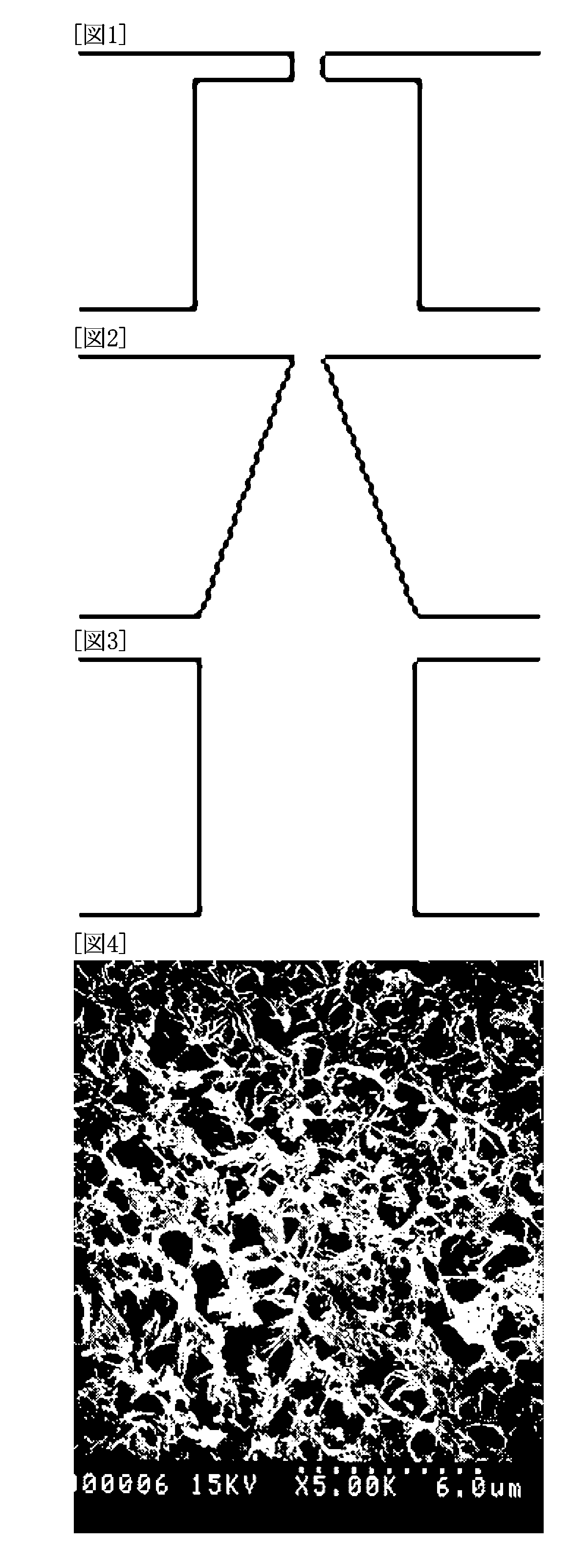
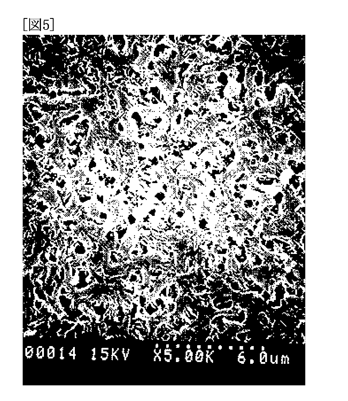
[0061]The hollow fiber membrane was observed with a scanning electron microscope (an SEM, hereinafter). A net-like structure was seen in the...

example 2

[0065]25 wt % of a polyvinylidene fluoride resin (SOLEF6020®) was dissolved in 75 wt % of diethylene glycol monoethyletheracetate by stirring under nitrogen atmosphere at 159° C., thereby obtaining a high temperature dope. The obtained high temperature dope was ejected from a coaxial double-slit spinneret together with triethylene glycol, which served as a hollow-portion-forming agent. Through an air gap of about 15 mm, the dope was led to a cooling bath consisting of a 10° C. aqueous solution containing 40 wt % of the diethylene glycol monoethyletheracetate to be solidified. The resulting fiber was wound at 5 m / min to obtain a hollow fiber membrane. The obtained hollow fiber membrane was washed with water to completely remove the solvent, and then dried to obtain a hollow fiber membrane 1.3 mm in outer diameter and 0.7 mm in inner diameter.

[0066]The hollow fiber membrane was observed with an SEM. A net-like structure was seen in the cross-section of the membrane, and there were no ...

example 3

[0067]The same process as in Example 2 was performed to obtain a hollow fiber membrane 1.3 mm in outer diameter and 0.7 mm in inner diameter, except that the concentration of diethylene glycol monoethyletheracetate in the cooling bath was 20 wt %.

[0068]The hollow fiber membrane was observed with an SEM. A net-like structure was seen in the cross-section of the membrane, and there were no 10 μm or greater macrovoids. A dense layer was formed on the peripheral surface with a depth of about 1.5 μm, and a homogeneous bulk layer was formed in the rest of the depth of the membrane to reach the inner surface. The porosity A of the bulk layer was 39%, and the membrane surface porosity B of the peripheral surface was 8%; that is, A was 4.9 times B. It was observed that the dense outer layer changed substantially discontinuously into the bulk layer. The pure water permeability was 24.1 m3 / (m2 per day) / 100 kPa at a water temperature of 25° C. The rejection of the Uniform Latex particle 0.039 μ...


PUM

PropertyMeasurementUnit
thicknessaaaaaaaaaa
porosityaaaaaaaaaa
porosityaaaaaaaaaa

Abstract

Problems: To provide a polyvinylidene fluoride microporous membrane which has high water permeability and separation performance and is excellent in mechanical and chemical strength; and a process for producing the film.Means for Solving Problems: An anisotropic polyvinylidene fluoride hollow fiber microporous membrane characterized in that the porosity of the cross-sectional bulk layer is higher than the membrane surface porosity of the outer layer and that in the cross section of the membrane, the dense microstructure of the outer surface changes substantially discontinuously into the coarse structure of the bulk layer. The microporous membrane can be produced by introducing by a dry-wet method a dope prepared by dissolving a polyvinylidene fluoride resin together with a water-soluble latent solvent at high temperature into a cooling bath consisting of water or a mixture thereof with a water-soluble latent solvent and subjecting the dope to membrane formation wherein the cross-sectional bulk layer is formed mainly by thermally-induced phase separation and the outer layer is formed mainly by nonsolvent-induced phase separation.

Description

TECHNICAL FIELD[0001]The present invention relates to a polyvinylidene fluoride hollow fiber microporous membrane and a process for production of the same. More specifically, the present invention relates to a highly anisotropic polyvinylidene fluoride hollow fiber microporous membrane having a net-like structure; and a production method thereof. The membrane is superior in permeability performance and has a sharp separation characteristic, high chemical resistance, and high mechanical strength.BACKGROUND ART[0002]Microporous membranes are used in many fields. The membrane can be used in fluid treatments as, for example, a supporting base of a reverse osmosis membrane or a nanofiltration membrane, an ultrafiltration membrane, and a microfiltration membrane. In other fields, the microporous membrane is used as a battery separator. The reverse osmosis membrane and the nanofiltration membrane are capable of removing salts and low-molecular-weight organic matter, and therefore are widel...

Claims


Application Information

Patent Timeline
Patent Type & Authority Applications(United States)
IPC IPC(8): B01D69/08
CPCB01D67/0009B01D69/08B01D71/34B01D2323/12B01D2325/02B01D67/0018B01D2325/24C02F1/444D01D5/24D01F6/12B01D2325/026Y02A20/131B01D2325/0283
Inventor ARIJI, AKIHIROYAMADA, HIDEKI
Owner TOYO TOYOBO CO LTD
Learn More