
Apparatus for Producing Trichlorosilane

Active Publication Date: 2009-10-29
MITSUBISHI MATERIALS CORP
View PDF3 Cites 6 Cited by
  • Summary
  • Abstract
  • Description
  • Claims
  • Application Information

AI Technical Summary

Benefits of technology

[0008]The present invention has been made in the light of the above-described problems. An object of the present invention is to provide an apparatus for producing trichlorosilane, which can effectively preheat the supply gas by heat exchange with the reaction product gas, and can be reduced in the size and the cost of the entire apparatus.
[0017]According to the apparatus for producing trichlorosilane of the present invention, since the apparatus for producing trichlorosilane has a structure in which the reaction product gas in a high-temperature state is returned through the return passageway to the discharge side passageway adjoining the supply side passageway, it is possible to efficiently preheat the supply gas by heat exchange of the supply gas with the reaction product gas while maintaining the reaction product gas in a high-temperature state before discharging from the reaction vessel. Since the heat exchange mechanism is disposed inside the reaction vessel, it is possible to reduce the entire size of the apparatus and the cost of the apparatus. Therefore, it is possible to obtain a high trichlorosilane-conversion ratio with good heating efficiency using the small-sized low cost apparatus.

Problems solved by technology

In the above conventional apparatus for producing trichlorosilane, although the supply gas is preheated by heat exchange by the heat exchanger disposed in the bottom portion of the reaction chamber, there is a problem that the temperature of the reaction product gas discharged from the reaction chamber decreases and thus a sufficient effect of preheating the supply gas cannot be obtained.
Also, there is a problem that it is necessary to dispose a separate heat exchanger outside the reactor, thus increasing the size of the entire apparatus and the cost of the apparatus.

Method used


Image

  • Apparatus for Producing Trichlorosilane
  • Apparatus for Producing Trichlorosilane
  • Apparatus for Producing Trichlorosilane

Examples


Embodiment Construction

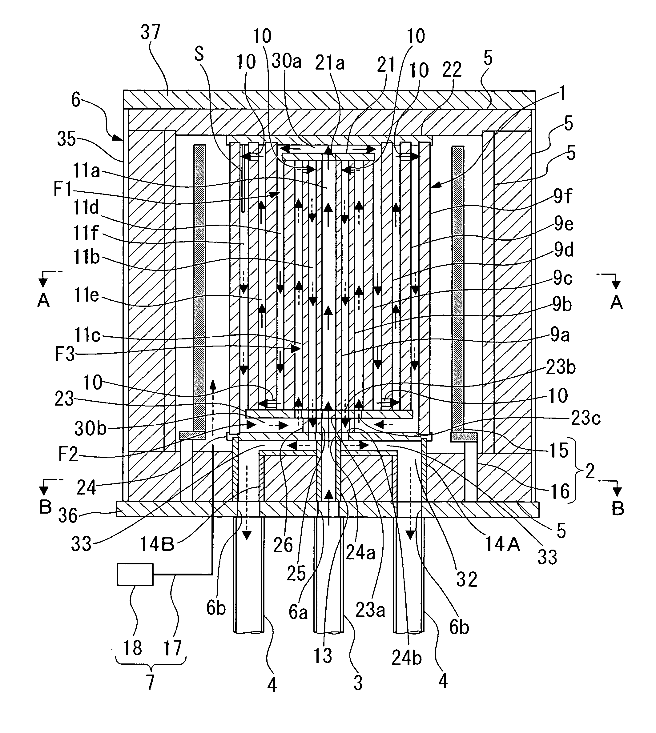
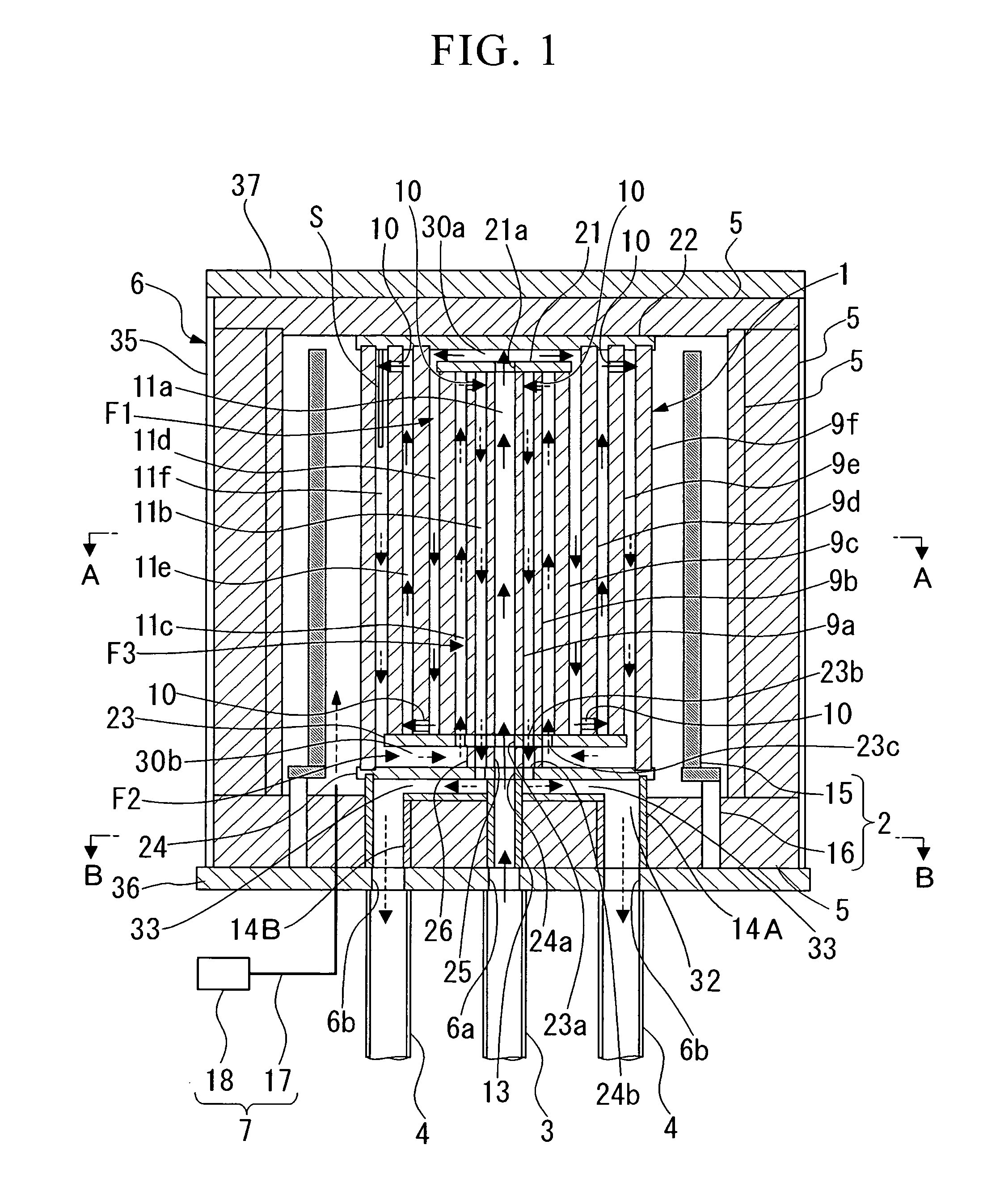
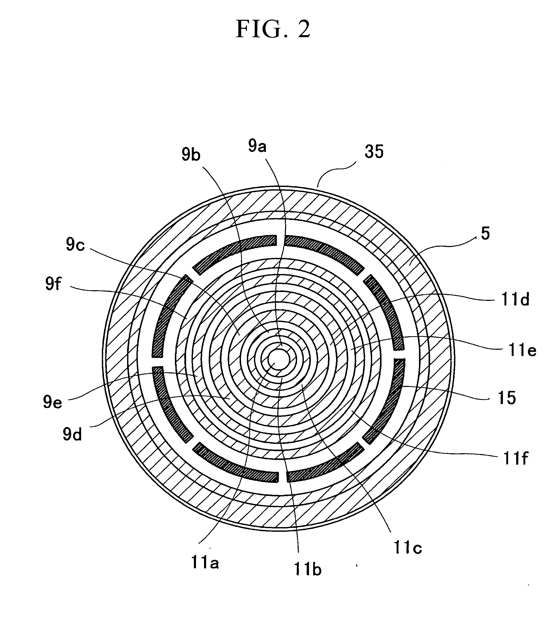
[0021]An embodiment of the apparatus for producing trichlorosilane of the present invention will be described below with reference to FIG. 1 or 2.

[0022]As shown in FIG. 1, the apparatus for producing trichlorosilane of the present embodiment includes a reaction vessel 1 in which a supply gas containing silicon tetrachloride and hydrogen is supplied to an internal reaction passageway to produce a reaction product gas containing trichlorosilane and hydrogen chloride; a heating mechanism 2 disposed in the periphery of the reaction vessel 1 for heating the reaction vessel 1 from the outside; a gas supply pipe 3 for supplying the supply gas in the reaction vessel 1; a plurality of gas discharge pipes 4 for discharging the reaction product gas from the reaction vessel 1 to the outside; a heat insulating material 5 disposed so as to cover the periphery of the reaction vessel 1 and the heating mechanism 2; a storage container 6 for storing the reaction vessel 1, the heating mechanism 2 and ...


PUM


Abstract

An apparatus for producing trichlorosilane, including: a reaction vessel in which a supply gas containing silicon tetrachloride and hydrogen is supplied to an internal reaction passageway to produce a reaction product gas containing trichlorosilane and hydrogen chloride; a heating mechanism that heats the interior of the reaction vessel; a gas supply section that supplies the supply gas in the reaction vessel; and a gas discharge section that discharges the reaction product gas from the reaction vessel to the outside, wherein the reaction passageway includes: a supply side passageway which is connected to the gas supply section at a central portion of the reaction vessel and flows the supply gas toward the outside while meandering in the reaction vessel; a return passageway which is connected to a downstream end of the supply side passageway and extends to the central portion of the reaction vessel; and a discharge side passageway that is disposed so as to be connected to a downstream end of the return passageway and to adjoin the supply side passageway of the central portion of the reaction vessel, the discharge side passageway being connected to the gas discharge section.

Description

TECHNICAL FIELD[0001]The present invention relates to an apparatus for producing trichlorosilane, which converts silicon tetrachloride into trichlorosilane.[0002]This application claims priority on Japanese Patent Application No. 2006-297035, filed Oct. 31, 2006, and on Japanese Patent Application No. 2007-259446, filed Oct. 3, 2007, the disclosure of which is incorporated by reference herein.BACKGROUND ART[0003]Trichlorosilane (SiHCl3), which is used as a raw material for the production of highly pure silicon (Si), can be produced by conversion through a reaction of silicon tetrachloride (SiCi4: tetrachlorosilane) with hydrogen.[0004]In other words, silicon is produced by the reductive reaction and the thermolysis reaction of trichlorosilane represented by reaction schemes (1) and (2) shown below, and trichlorosilane is produced by the conversion reaction represented by reaction scheme (3) shown below.SiHCl3+H2→Si+3HCl  (1)4SiHCl3→Si+3SiCl4+2H2  (2)SiCl4+H2→SiHCl3+HCl  (3)[0005]As ...

Claims


Application Information

Patent Timeline
IPC IPC(8): B01J19/00
CPCC01B33/1071B01J12/007B01J19/02B01J19/243B01J2219/00135B01J2219/00155B01J2219/0272C01B33/10757
Inventor ISHII, TOSHIYUKIITO, HIDEOSHIMIZU, YUJI
Owner MITSUBISHI MATERIALS CORP
Learn More