Method and Apparatus for Processing a Pulsatile Biometric Signal

a biometric signal and processing method technology, applied in the field of pulse oximetry signal processing, can solve the problems of difficult avoiding of detector unit saturation, difficult avoiding of saturation, difficult avoiding of saturation, etc., to achieve the effect of increasing the dc component of the signal, avoiding saturation, and avoiding saturation

Inactive Publication Date: 2009-10-15
CONMED CORP
View PDF5 Cites 39 Cited by
  • Summary
  • Abstract
  • Description
  • Claims
  • Application Information

AI Technical Summary

Benefits of technology

[0006]Avoiding detector unit saturation can be difficult with living subjects having a high amount of pigmentation (e.g., subjects with dark skin) because the AC / DC ratio of a signal from the light reflected from the subjects can be much lower than normal. Avoiding saturation can also be difficult when there is a relatively high amount of biological tissue (e.g., fat, fluid, muscle, etc.) that contains a limited amount of arterial vessels. In that situation, the DC component can be larger than normal, and the AC component can be even smaller (e.g., 20 on a scale of 1 to 1,000,000). Avoiding saturation can also be difficult when the tissue under the sensor swells with fluid (e.g., edema which is associated with burn patients). The fluid and tissue can reflect more light, increasing the DC component of the signal, while decreasing an AC arterial signal content (e.g., AC component of the signal). Therefore, it can be difficult to avoid detector unit saturation while still having enough of an AC component (e.g., the pulsating part) of the signal to calculate accurately the pulse rate and the oxygen saturation in a patient having a high amount of pigmentation, high amount of biological tissue, edema, or any combination thereof. Techniques to avoid detector unit saturation can be beneficial if used in pulse oximetry systems used on patients having edema and can also allow for the placement of a sensor on a part of the body having a greater amount of pigmentation (e.g., on the forehead, ear or nose of the living subject) as compared to another part of the body (e.g., finger), on a part of the body having a high amount of biological tissue.
[0012]In some embodiments, determining whether at least one sample of light approaches a saturation level of a detector unit includes determining if the at least one sample of light has reached a threshold value. An accumulation time can adjusted to prevent saturation of a detector unit by lowering the accumulation time when at least one sample of light reaches a threshold value. In some embodiments, the threshold value is about 70% to about 85% of a saturation level of a detector unit. A step of lowering an accumulation time can include activating a light source (e.g., one or more LEDs in a pulse oximetry system) for a shorter period of time (e.g., shortening an activation period of the light source). In some embodiments, an accumulation time is adjusted by lowering the accumulation time until the accumulation time reaches a minimum value. In some embodiments, an accumulation time is 400 ms (e.g., initial accumulation time) and the minimum value for the activation time is 200 ms. A power level of the transmitted light (e.g., activated light source) can be adjusted to avoid saturation of a detector unit if the accumulation time has been lowered to a minimum value.

Problems solved by technology

Avoiding detector unit saturation can be difficult with living subjects having a high amount of pigmentation (e.g., subjects with dark skin) because the AC / DC ratio of a signal from the light reflected from the subjects can be much lower than normal.
Avoiding saturation can also be difficult when there is a relatively high amount of biological tissue (e.g., fat, fluid, muscle, etc.) that contains a limited amount of arterial vessels.
Avoiding saturation can also be difficult when the tissue under the sensor swells with fluid (e.g., edema which is associated with burn patients).
Therefore, it can be difficult to avoid detector unit saturation while still having enough of an AC component (e.g., the pulsating part) of the signal to calculate accurately the pulse rate and the oxygen saturation in a patient having a high amount of pigmentation, high amount of biological tissue, edema, or any combination thereof.

Method used


Image

  • Method and Apparatus for Processing a Pulsatile Biometric Signal
  • Method and Apparatus for Processing a Pulsatile Biometric Signal
  • Method and Apparatus for Processing a Pulsatile Biometric Signal

Examples


Embodiment Construction

[0025]While the illustrative embodiments disclosed herein are described in the context of pulse oximetry, the illustrative embodiments can be applied in other contexts that relate to signal processing of a pulsatile biometric signal. The illustrative embodiments can be applied to, for example, a reflective pulse oximetry system or a transmission pulse oximetry system.

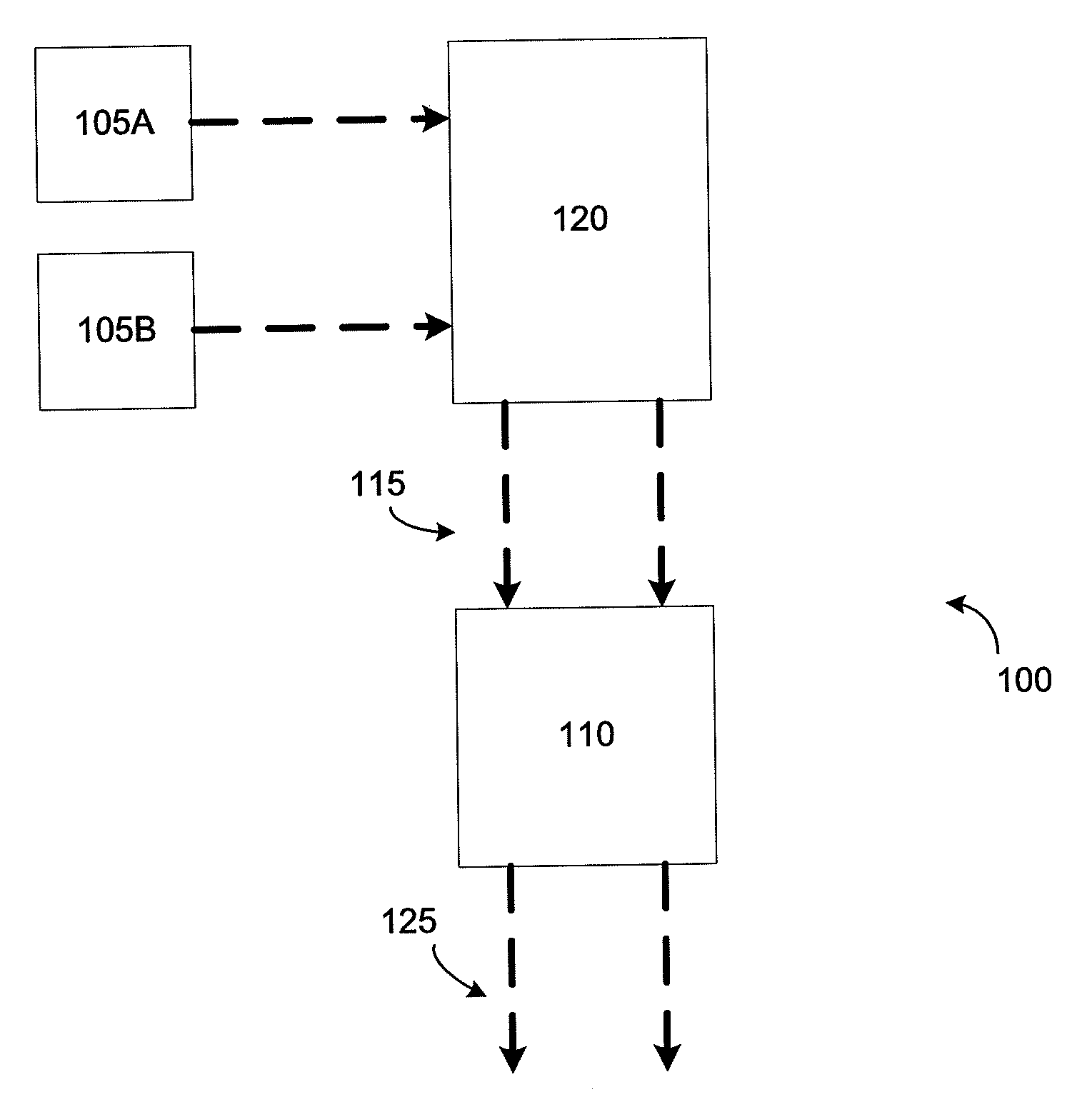
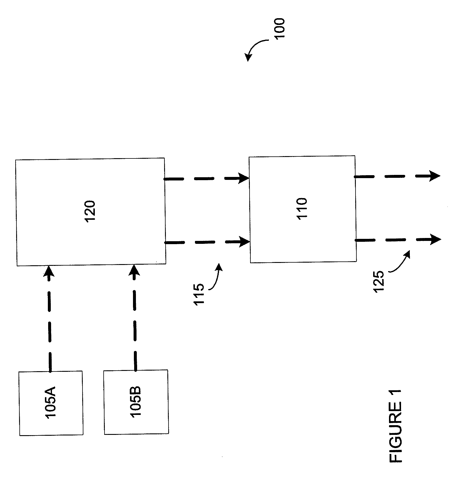
[0026]FIG. 1 is a schematic of a pulse oximetry system 100. A pulse oximetry system can detect samples using both red and infrared (IR) light at a plurality of times per second. The system can include a plurality of light sources 105A and 105B (e.g., a source of red light, a source of infrared light, etc.) that can be activated to transmit light for a period of time (e.g., an accumulation time). A detector unit 110 (e.g., photodetector and a preamplifier unit) can detect (e.g., sense or acquire) light reflected 115 (e.g., which can include the reflected red light or infrared light) from the living subject 120 and can co...


PUM


Abstract

A method for processing a pulsatile signal of light reflected from a living subject can include the step of activating a light source to transmit light to the living subject during an accumulation time. The method can include the step of detecting at least one sample of the light reflected from the living subject using a detector unit and determining if the sample(s) of light approaches a saturation level of the detector unit. The method can include the step of adjusting the accumulation time to prevent saturation of the detector unit if it has been determined that the at least one sample of light has approached a saturation level of the detector unit.

Description

CROSS-REFERENCE TO RELATED APPLICATION[0001]This application claims the benefit of and priority to U.S. provisional patent Application No. 60 / 987,941 filed Nov. 14, 2007 entitled “Reflectance Oximetry Signal Processing,” which is owned by the assignee of the instant application and the disclosure of which is incorporated herein by reference in its entirety.FIELD OF THE INVENTION[0002]The invention relates generally to a method and apparatus for processing a pulsatile biometric signal. Specifically, the invention relates to pulse oximetry signal processing.BACKGROUND OF THE INVENTION[0003]Pulse oximetry is a non-invasive diagnostic procedure for measuring the level of oxygen saturation in a patient's arterial blood. Pulse oximetry is based on the principle of passing light energy from at least two wavelengths to a light-absorptive physiologic medium, acquiring the reflected (or transmitted) emitted light in response to the light absorption, and calculating the oxygen saturation level...

Claims


Application Information

Patent Timeline
Patent Type & Authority Applications(United States)
IPC IPC(8): A61B5/1455
CPCA61B5/14551A61B5/02416
Inventor WASSERMAN, YORAMLOWERY, GUY RUSSELL
Owner CONMED CORP
Why Eureka
Try Eureka