Resonance DC/DC Converter and Control Method Thereof

Active Publication Date: 2009-09-03
VERTIV CORP
View PDF12 Cites 19 Cited by
  • Summary
  • Abstract
  • Description
  • Claims
  • Application Information

AI Technical Summary

Benefits of technology

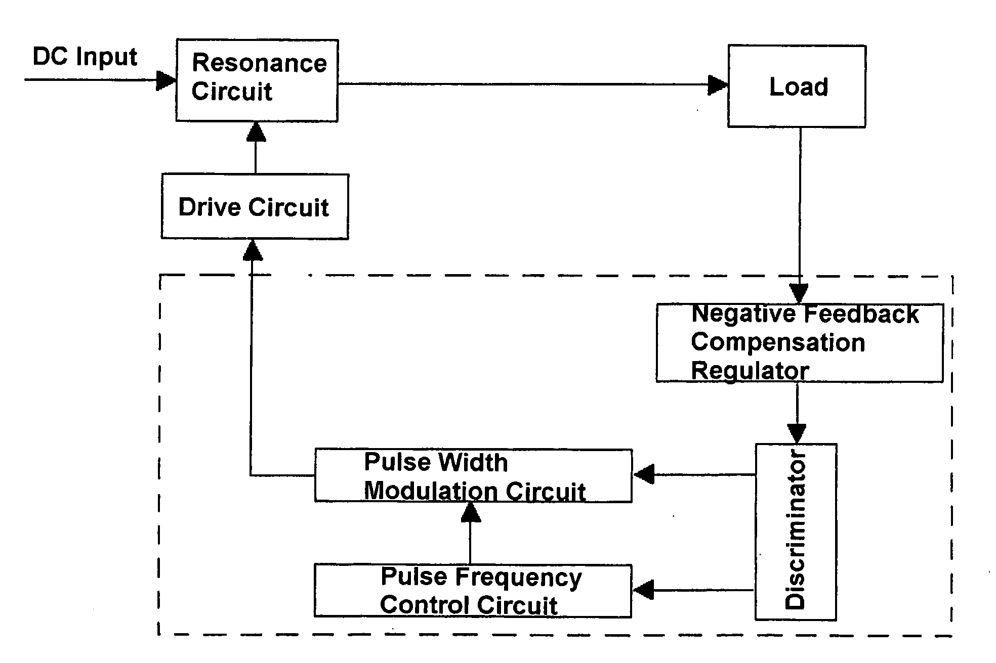
[0020]With the above technical solution, the present invention has the following advantageous technical effects:1) The PWM controlling mode is introduced into the controlling mode of the resonance DC / DC converter, realizing the two controlling modes of PFM and PFM+PWM. That is, the PFM controlling mode is used when the operating frequency of the power supply is relatively low, and the PFM+PWM controlling mode is introduced when the operating frequency of the power supply is too high. And the frequency can be fixed when the frequency is even higher, entering the PWM controlling mode. Therefore, the problem of the resonance converter is resolved, that is, the problem that the operating frequency is too high and the loss of the circuit is too large in case of light load and non-load, thereby enhancing the regulation ability of the output voltage of the resonance circuit, and expanding the voltage output range effectively.2) The two modes of the PFM controlling and the PFM+PWM controlling are selectively parallel in logistic, and can be realized by adopting preferably the mode that the pulse frequency control circuit and the pulse width modulation circuit are connected in series. The preferred circuit avoids the use of many logical gate devices and the multi-channel negative feedback compensation regulators, and thus it is simple. And the switching of the two controlling modes is smooth, and the reliability and the dynamic characteristic of these two modes are very good.

Problems solved by technology

However, the increase of switching frequency will result in the big loss of the switch device, and this can not be resolved by the conventional BUCK converter, while the resonance converter can resolve this problem properly.
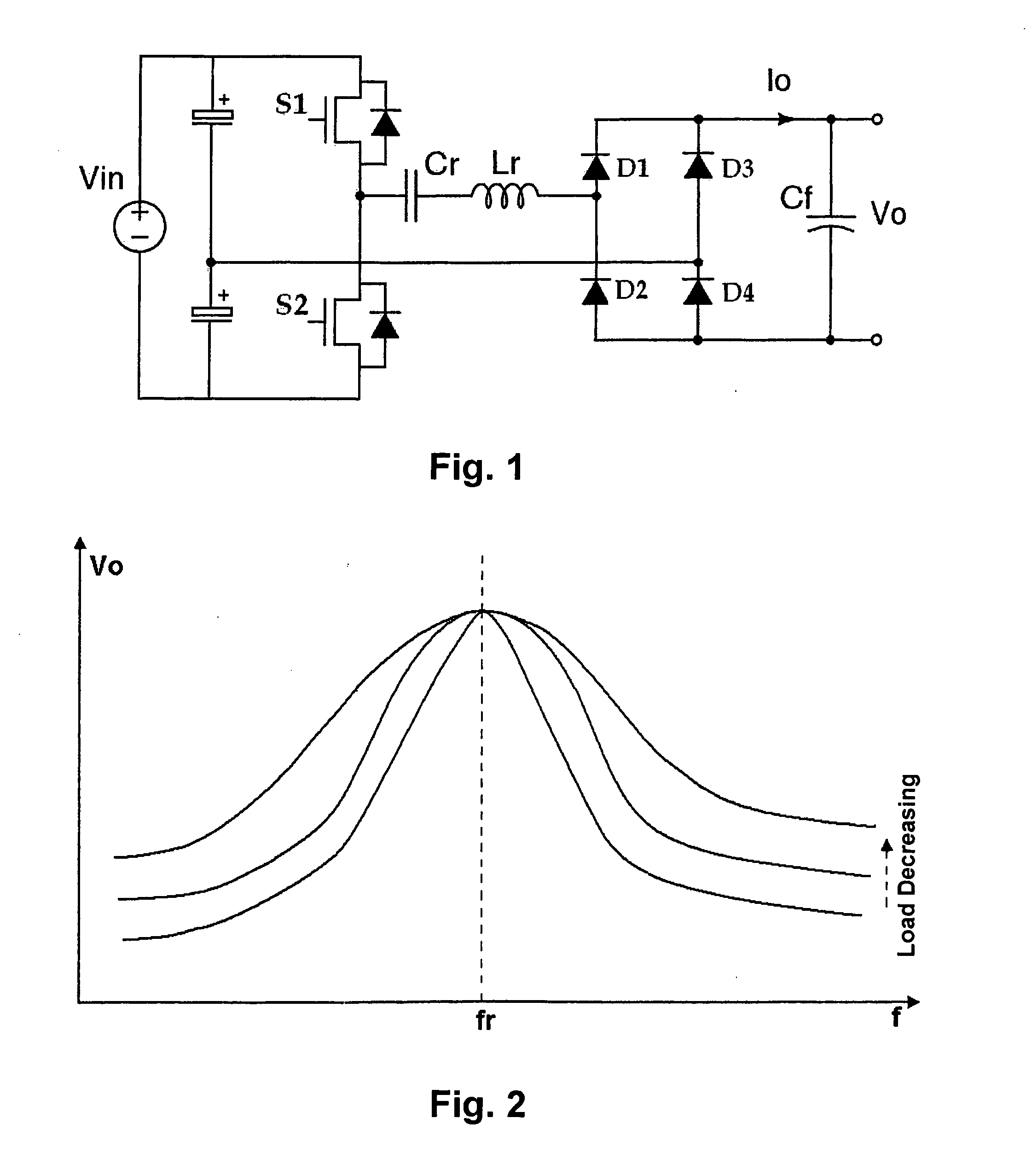
As seen from FIG. 2, a key difficult problem of the series resonance converter is that the output voltage is difficult to be stabilized under the condition of the light load and non-load.
However, overbroad of the range of the operating frequency will cause difficulty of optimization of the magnetic device, and the higher the operating frequency is, the larger the loss of the circuit is.
In addition, when the load is close to non-load, the output voltage may rise instead, thereby resulting in impossible control of negative feedback.
However, this operation may increase non-load loss, and decrease the efficiency of the power supply.
In sum, the pure pulse frequency control will result in overbroad of the range of the operating frequency, even failure, and cause the problems of difficulty of optimization of the magnetic device and the large loss of the circuit, and will result in difficulty of designing a feedback control.
Therefore, the simple frequency modulated control cannot fulfill the need of stabilizing the voltage at the condition of light load or non-load.
In theory, there are similar problems in all of the frequency modulation control resonance circuit.

Method used


Image

  • Resonance DC/DC Converter and Control Method Thereof
  • Resonance DC/DC Converter and Control Method Thereof
  • Resonance DC/DC Converter and Control Method Thereof

Examples


Embodiment Construction

[0031]A method for controlling a resonance DC / DC converter is provided, in which a output voltage is regulated by changing on-frequency of an input switch device in the resonance circuit, and the duty ratio of the switch device is regulated based on a feedback signal from the load circuit, so that the range of output voltage of the resonance circuit is expanded.

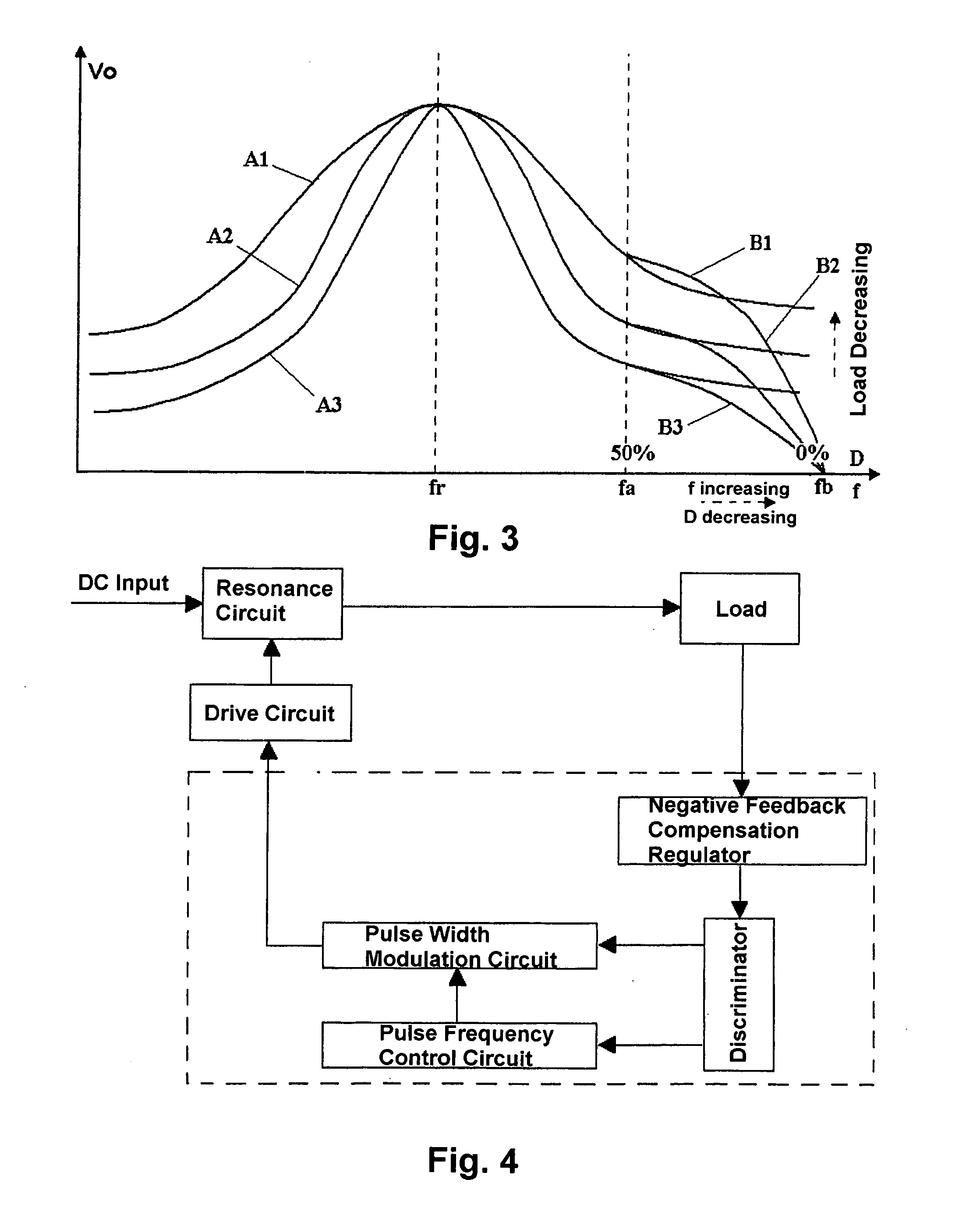
[0032]Now take the half bridge series resonance circuit of FIG. 1 as an example, and the curves A1˜A3 in FIG. 3 show the characteristics of output voltage Vo versus frequency f of the circuit when it is controlled with only PFM control mode in deferent load conditions, wherein the duty ratio is 50%. It can be seen that as the load decreases, the curve of Vo tends to be flat, and is hard to be stabilized by increasing the operating frequency. Curves B1, B2, B3 in FIG. 3 show the characteristics of output voltage Vo versus duty ratio D and frequency f when the switching frequencies of curves A1˜A3 are above fa, after the circui...


PUM


Abstract

The present invention refers to a method for controlling a resonance DC / DC converter, which adjusts an output voltage by changing a turn-on frequency of input switch devices of a resonance circuit of the converter, and extends the range of the output voltage of the resonance circuit by adjusting the duty ratio of the switch devices based on the feedback signal of the load circuit. The present invention also provides the resonance DC / DC converter structure using the controlling method. The advantage of the present invention lies in the use of two modes of frequency modulation and frequency modulation plus pulse width modulation to control the resonance DC / DC converter; the use of the frequency modulation controlling mode when the operating frequency of the power supply is low, and introducing the frequency modulation plus pulse width modulation controlling mode when the operating frequency of the power supply is too high. As a result, the problem of the resonance converter, that is, the high operating frequency and the big loss of the circuit when the circuit operates at a light load and non-load, can be solved, and thus the regulation ability for the output voltage of the resonance circuit is enormously improved, and the output range of the voltage is effectively expanded.

Description

FIELD OF THE INVENTION[0001]The present invention relates to DC power supply converting technique, and more particularly, to a resonance DC / DC converter and a method for controlling the same.BACKGROUND OF THE INVENTION[0002]At present, miniaturization and high-frequency are the trend of development of power supplies. However, the increase of switching frequency will result in the big loss of the switch device, and this can not be resolved by the conventional BUCK converter, while the resonance converter can resolve this problem properly.[0003]Taking the series resonance converter as an example, the series resonance DC / DC converter adopts resonance converting technique. As the resonance element operates at the sine resonance state, the voltage across the switch device is naturally cross-zero, thereby realizing zero-voltage turn-on, and very small loss of the power supply. This topology usually utilizes pulse frequency modulation (PFM) mode, stabilizing the output voltage by changing ...

Claims


Application Information

Patent Timeline
IPC IPC(8): G05F1/10
CPCH02M3/337H02M3/3376Y02B70/1433Y02B70/126Y02B70/1491H02M1/4241H02M2001/0058Y02B70/10H02M1/0058H02M3/01H02M3/33571
Inventor LIU, ZHIYUZHU, CHUNHUIZHAO, HAIZHOU
Owner VERTIV CORP
Why Eureka
Try Eureka