Projection optical system and image display device
a technology of applied in the field of projection optical system and image display device, can solve the problems of increased size, high center of device, and large device height, and achieve the effect of cost advantage, compactness and setting stability of the projector main body
- Summary
- Abstract
- Description
- Claims
- Application Information
AI Technical Summary
Benefits of technology
Problems solved by technology
Method used
Image
Examples
first embodiment
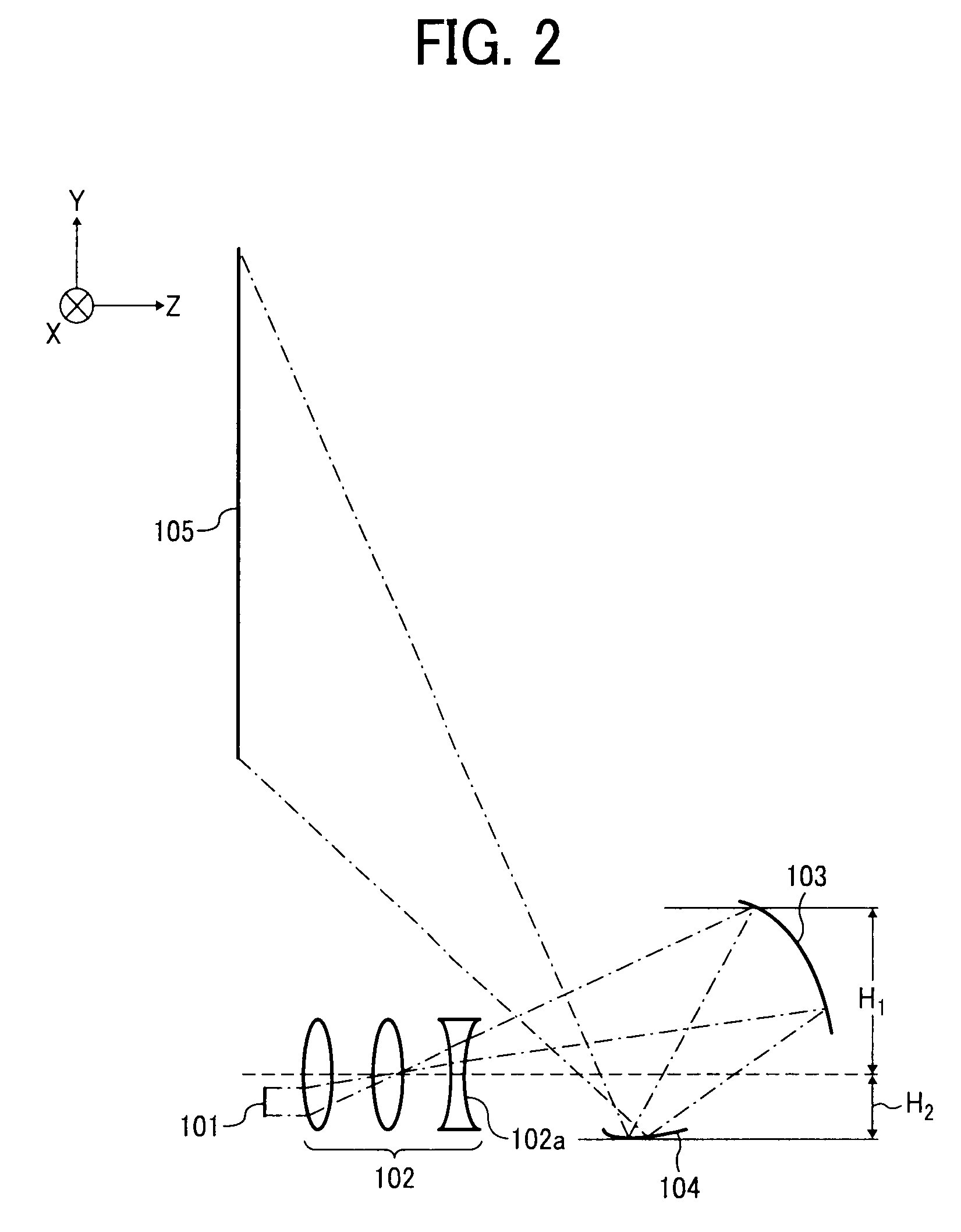
[0030]A first embodiment will be explained below with reference to FIGS. 1-3.
[0031]A projection optical system 1 of a front projector according to the first embodiment includes a projector main body 2 which has one conjugate plane, and a screen 105 which forms another conjugate plane.
[0032]The projector main body 2 includes a case 110. An image forming element 101, a first optical system 102 which has a plurality of lenses, and a second optical system 112 are housed in the case 110.
[0033]The second optical system 112 has a first reflecting surface 103 with positive power corresponding to the first optical system 102, and a second reflecting surface 104 with optical power corresponding to the screen 105. Both the reflecting surfaces 103 and 104 have anamorphic adjustable surface shapes.
[0034]Here, “a first reflecting surface corresponding to a first optical system” represents a reflecting surface into which light that exits from a first optical system enters first, and “a second refl...
second embodiment
[0059]A second embodiment will be explained with reference to FIG. 4 and FIG. 5. Similar parts to the above-mentioned embodiment are assigned the same reference members, and a detailed explanation is omitted. Hereafter, only main parts will be explained.
[0060]FIG. 4 is an overall view of an image display device 400 according to the present embodiment, and FIG. 5 is an enlarged view of a part excluding a screen 405 as illustrated in FIG. 4.
[0061]Light flux emitted from an image forming element 401 which is represented by a transmissive liquid crystal panel, a reflective liquid crystal panel, or DMD, enters into a first optical system 402 which is a coaxial optical system formed of lenses only.
[0062]In the present embodiment, the first optical system 402 is formed of lenses only, a device which folds an optical path using such as a reflecting surface or a diffractive surface is preferable as well, only if the desired imaging performance is fulfilled. In addition, the first optical sys...
fourth embodiment
[0074]the present invention will be explained with reference to FIG. 7.
[0075]A projector main body 3 in a projection optical system according to the fourth embodiment includes a case 610, which is in a rectangular solid shape and is not convexoconcave at its outer surface, compared with the case 110 illustrated in FIG. 1. The image forming element 101, the first optical system 102, and the second optical system 112 are housed in the case 610 without a bulge outside.
[0076]The case 610 is formed in the rectangular solid shape, corresponding to a height of the first optical system 102 in the vertical direction of an image on the screen 105. That is, a height of the case 610 in the vertical direction is set to the minimum height required to house the first optical system 102 without useless space, and the compactness is achieved.
[0077]The first reflecting surface 103 corresponding to the first optical system 102 of the second optical system 112 is provided to be pivotally supported at a...
PUM
 Abstract
Description
Claims
Application Information
 - R&D
- Intellectual Property
- Life Sciences
- Materials
- Tech Scout
- Unparalleled Data Quality
- Higher Quality Content
- 60% Fewer Hallucinations
Browse by: Latest US Patents, China's latest patents, Technical Efficacy Thesaurus, Application Domain, Technology Topic, Popular Technical Reports.
© 2025 PatSnap. All rights reserved.Legal|Privacy policy|Modern Slavery Act Transparency Statement|Sitemap|About US| Contact US: help@patsnap.com


