
Receiving member, display having the same, and method thereof

a technology of receiving member and display, which is applied in the direction of electrical apparatus casing/cabinet/drawer, instruments, manufacturing tools, etc., can solve problems such as malfunction of the control board, and achieve the effect of reducing the characteristics (uniformity between lamps) of a plurality of lamps contained within the conventional metallic receiving member, increasing leakage current, and increasing the temperature of the control board

Inactive Publication Date: 2009-07-16
SAMSUNG ELECTRONICS CO LTD
View PDF19 Cites 17 Cited by
  • Summary
  • Abstract
  • Description
  • Claims
  • Application Information

AI Technical Summary

Benefits of technology

[0007]It is has been determined herein that a parasitic capacitance is generated between a conventional metallic receiving member and a lamp contained therein, so that a leakage current is increased. This causes characteristics (uniformity between lamps) of a plurality of lamps contained within the conventional metallic receiving member to be lowered. The conventional metallic receiving member does not shield heat from the lamps, and the heat is directly conducted to a control board attached on an outside of the bottom plate of the conventional metallic receiving member. Therefore, the temperature of the control board is increased, thereby resulting in malfunction of the control board.
[0008]The present invention provides a receiving member having a ground metal portion provided in an inside thereof and manufactured using an insulated synthetic resin so that the weight of the receiving member can be reduced, characteristics of lamps can be enhanced, and heat radiated to the outside of the receiving member can be reduced.

Problems solved by technology

Therefore, the temperature of the control board is increased, thereby resulting in malfunction of the control board.

Method used


Image

  • Receiving member, display having the same, and method thereof
  • Receiving member, display having the same, and method thereof
  • Receiving member, display having the same, and method thereof

Examples


Embodiment Construction

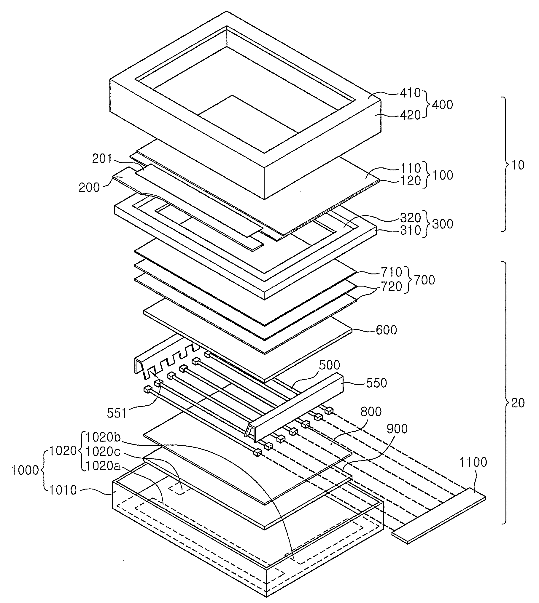
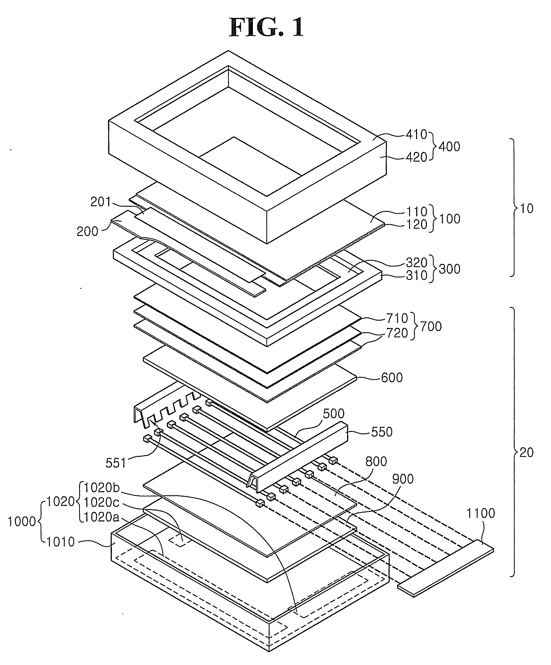
[0037]Hereinafter, exemplary embodiments of the present invention will be described in detail with reference to the accompanying drawings. However, the present invention is not limited to the embodiments disclosed below but may be implemented into different forms. These embodiments are provided only for illustrative purposes and for full understanding of the scope of the present invention by those skilled in the art.

[0038]It will be understood that when an element or layer is referred to as being “on,”“connected to” or “coupled to” another element or layer, it can be directly on, connected or coupled to the other element or layer or intervening elements or layers may be present. In contrast, when an element is referred to as being “directly on,”“directly connected to” or “directly coupled to” another element or layer, there are no intervening elements or layers present. Like numbers refer to like elements throughout. As used herein, the term “and / or” includes any and all combination...


PUM

PropertyMeasurementUnit
conductiveaaaaaaaaaa
shapeaaaaaaaaaa
weightaaaaaaaaaa

Abstract

The present invention relates to a receiving member which accommodates a display panel which displays an image. The receiving member includes an insulated body portion having a bottom plate and sidewalls to define a receiving space, and at least one ground metal portion provided at a region of the insulated body portion, the at least one ground metal portion formed integrally with the insulated body portion. Accordingly, the body portion of the receiving member is formed of an insulated material, thereby reducing the weight of the receiving member and improving heat radiation. Further, a local metal portion is provided in the receiving member, thereby improving electromagnetic interference (“EMI”) and electrostatic discharge performances of elements such as a control board.

Description

[0001]This application claims priority to Korean Patent application No. 10-2008-0004406, filed on Jan. 15, 2008, and all the benefits accruing therefrom under 35 U.S.C. 119, the contents of which in its entirety are herein incorporated by reference.BACKGROUND OF THE INVENTION[0002]1. Field of the Invention[0003]The present invention relates to a receiving member, a display having the same, and a method thereof, and more particularly, to a receiving member having a light weight and improving characteristics of backlight assembly, a display having the receiving member, and a method of manufacturing the receiving member.[0004]2. Description of the Related Art[0005]A flat panel display includes a display panel having a flat panel shape and a receiving member for accommodating the display panel. The receiving member accommodates a display panel therein to fix the display panel and to protect it against external impact.[0006]As the size of a display panel is increased, the size of a recei...

Claims


Application Information

Patent Timeline
Patent Type & Authority Applications(United States)
IPC IPC(8): G02F1/1333H05K5/00H01S4/00B28B19/00
CPCG02F1/133308G02F1/133608G02F1/13452G02F2001/133314Y10T29/49002G02F2001/133628G02F2201/503H05K7/20963H05K9/0054G02F2001/133322G02F1/133322G02F1/133314G02F1/133628G02F1/1333
Inventor KIM, YUN-NAMYEON, YEUN-MOSUNG, HWAN-JUNYUN, JIN-MAN
Owner SAMSUNG ELECTRONICS CO LTD
Learn More