Eureka AIR delivers breakthrough ideas for toughest innovation challenges, trusted by R&D personnel around the world.

Exterior wall construction product

a construction product and exterior wall technology, applied in the direction of walls, girders, building repairs, etc., can solve the problems of limited orthogonal movement of the studs, difficult to identify the proper location for the attachment of the exterior sheathing element, etc., and achieve the effect of adding stability

Active Publication Date: 2009-07-16
CEMCO LLC
View PDF102 Cites 76 Cited by
  • Summary
  • Abstract
  • Description
  • Claims
  • Application Information

AI Technical Summary

Benefits of technology

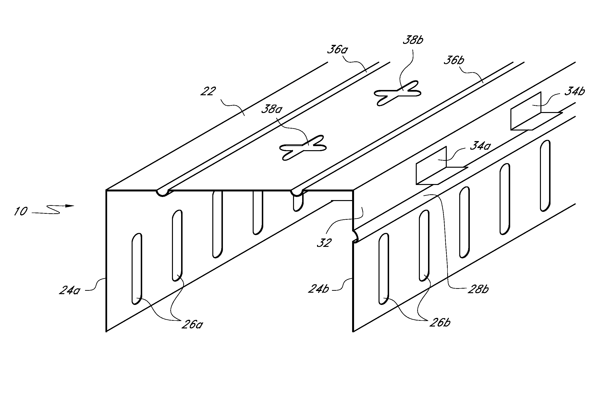
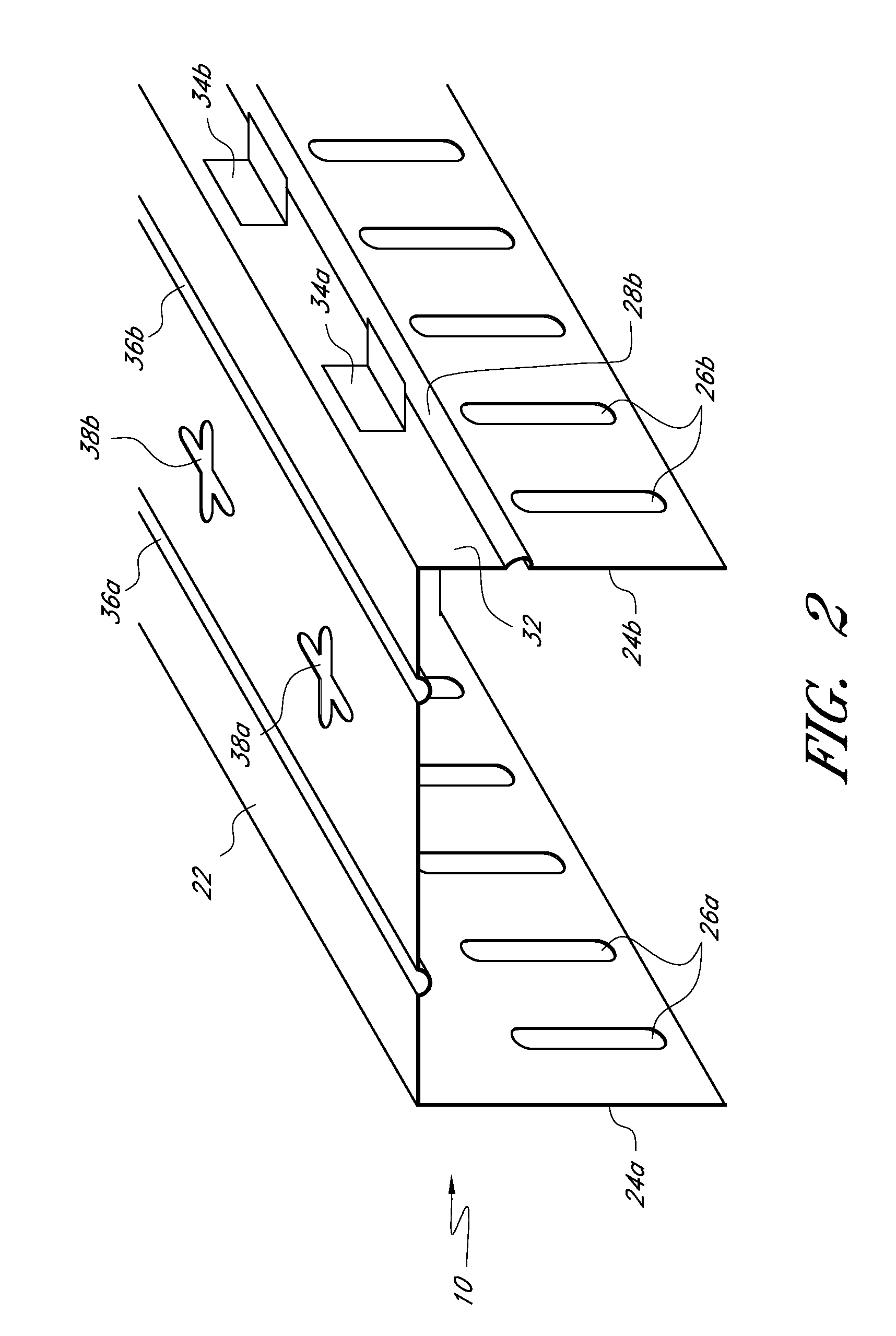
[0009]This application is directed toward an improved slotted track device and system capable of use in building construction. It is well-suited for use in the exterior wall of a building, but can be used in other applications as well. The device includes a plurality of slots located along at least one flange of the slotted track. The slots permit attachment of the slotted track to a wall stud or studs. The slots also allow for generally orthogonal movement of the wall studs relative to the slotted track during an earthquake or some other event where movement of the studs is desired.
[0011]In one embodiment, an outward rib along the flange of the track has a secondary function in providing a ridge against which an exterior sheathing element can rest. This ridge helps to ensure proper alignment or placement of the exterior sheathing element during attachment of the sheathing element to the slotted track, and can have a triangular-shaped cross-section.
[0013]In at least one embodiment the slotted track also comprises a plurality of second slots laterally positioned along the web of the track which permit attachment of the slotted track to a floor or other wall element. The plurality of second slots can be of various shapes, and can allow for drift movement of the track in various directions. For example, in one embodiment the second slots have a generally cross-like pattern, allowing for drift movement in multiple directions.

Problems solved by technology

It has been discovered by the present inventor that it is also often difficult to identify the proper location for attachment of an exterior sheathing element along the flange of a slotted track.
If the sheathing elements are misaligned and overlap a portion of the plurality of slots, the generally orthogonal movement of the studs can be limited due to interference between the stud fastener, which passes through one of the plurality of slots, and the sheathing element.

Method used


Image

  • Exterior wall construction product
  • Exterior wall construction product
  • Exterior wall construction product

Examples


Embodiment Construction

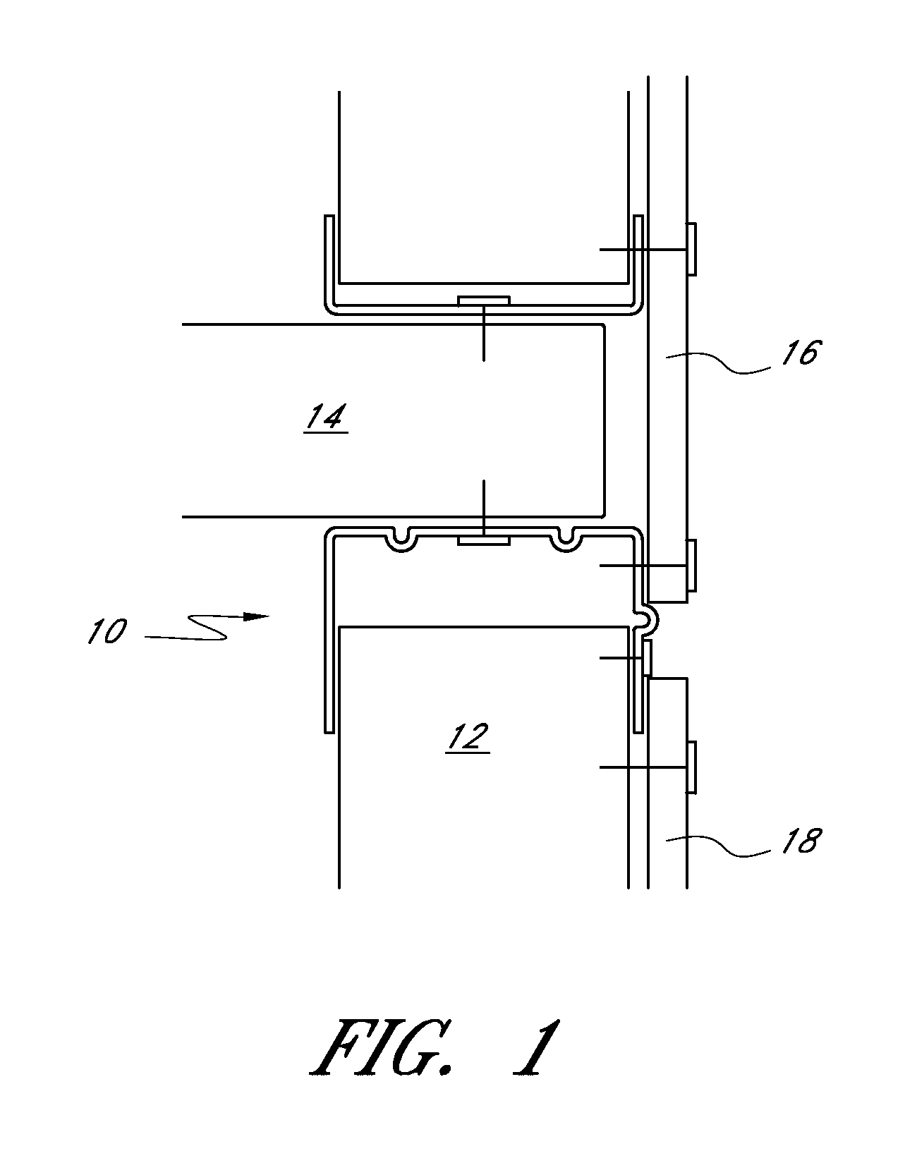
[0027]Referring to FIG. 1, the inventive slotted track 10 can be used with a wall stud 12, a floor slab 14, and two pieces of exterior sheathing elements 16 and 18. In use, the slotted track 10 is connected to the bottom surface of floor slab 14 by an acceptable fastening means. In the illustrated arrangement, the floor slab 14 is solid; however, it is also possible to use the track 10 with other types of floors (e.g., fluted floor decks) and other suitable structures, as well. The two exterior sheathing elements 16 and 18 are positioned and attached alongside the exterior portion of the slotted track 10 such that a lower end of upper sheathing element 16 ends just prior to a plurality of slots (not shown in FIG. 1) along a portion of one flange of the slotted track 10.

[0028]Referring to FIG. 2, an embodiment of the slotted track 10 comprises a web 22, two flanges 24a and 24b, and a plurality of slots 26a and 26b along each of the flanges 24a and 24b. These slots 26a and 26b are con...


PUM


Abstract

The present application is directed toward slotted tracks, in particular slotted tracks for an exterior wall application. Embodiments can include tracks with elongate reinforcing ribs on the tracks' flanges and / or web, tabs and / or protruding ribs for supporting and positioning exterior sheathing elements, second slot patterns along the length of the web of the track to allow for attachment and drift movement of the track with another wall component, and guide marks to identify proper locations for attachment of fasteners.

Description

RELATED APPLICATIONS [0001]This application is a continuation-in-part of U.S. patent application Ser. No. 12 / 039,685, filed Feb. 28, 2008, the entire contents of which are incorporated by reference herein, which claims benefit under 35 U.S.C. §119(e) to U.S. Provisional Patent Application No. 61 / 021,418, filed on Jan. 16, 2008, the entire contents of which are incorporated by reference herein. Also incorporated herein in their entireties by reference are U.S. application Ser. No. 12 / 013,361, entitled Fire Rated Wall Construction Product, filed Jan. 11, 2008, and U.S. application Ser. No. 12 / 040,658, entitled Two-Piece Track System, filed Feb. 29, 2008.BACKGROUND OF THE INVENTION [0002]1. Field of the Invention[0003]This application is directed toward a header track device for use in building construction, particularly for use in the exterior wall of a building.[0004]2. Description of the Related Art[0005]Header tracks, including slotted tracks, are commonly used in the construction ...

Claims


Application Information

Patent Timeline
IPC IPC(8): E04B2/56E04C3/00E04B1/38E04C2/38
CPCE04B1/24E04B2/789E04B2001/2469E04B2001/2481E04C3/07E04C2003/0421E04C2003/0434E04C2003/0473E02D37/00E04B1/14E04B2/847E04B2/90E04B2/96E06B3/5427E04B2/768E04B1/943
Inventor PILZ, DON A.POLIQUIN, RAYMOND E.SESMA, FERNANDO HERNANDEZ
Owner CEMCO LLC
Why Eureka
Eureka Blog
Learn More