Eureka AIR delivers breakthrough ideas for toughest innovation challenges, trusted by R&D personnel around the world.

Coating Apparatus and Coating Method

a technology of coating apparatus and coating method, which is applied in the direction of coating, instruments, pretreatment surfaces, etc., can solve the problems of non-uniform film thickness, increase in the rotational speed of the wafer, and non-uniform film thickness, so as to achieve effective inhibition

Inactive Publication Date: 2009-06-25
TOKYO ELECTRON LTD
View PDF20 Cites 18 Cited by
  • Summary
  • Abstract
  • Description
  • Claims
  • Application Information

AI Technical Summary

Benefits of technology

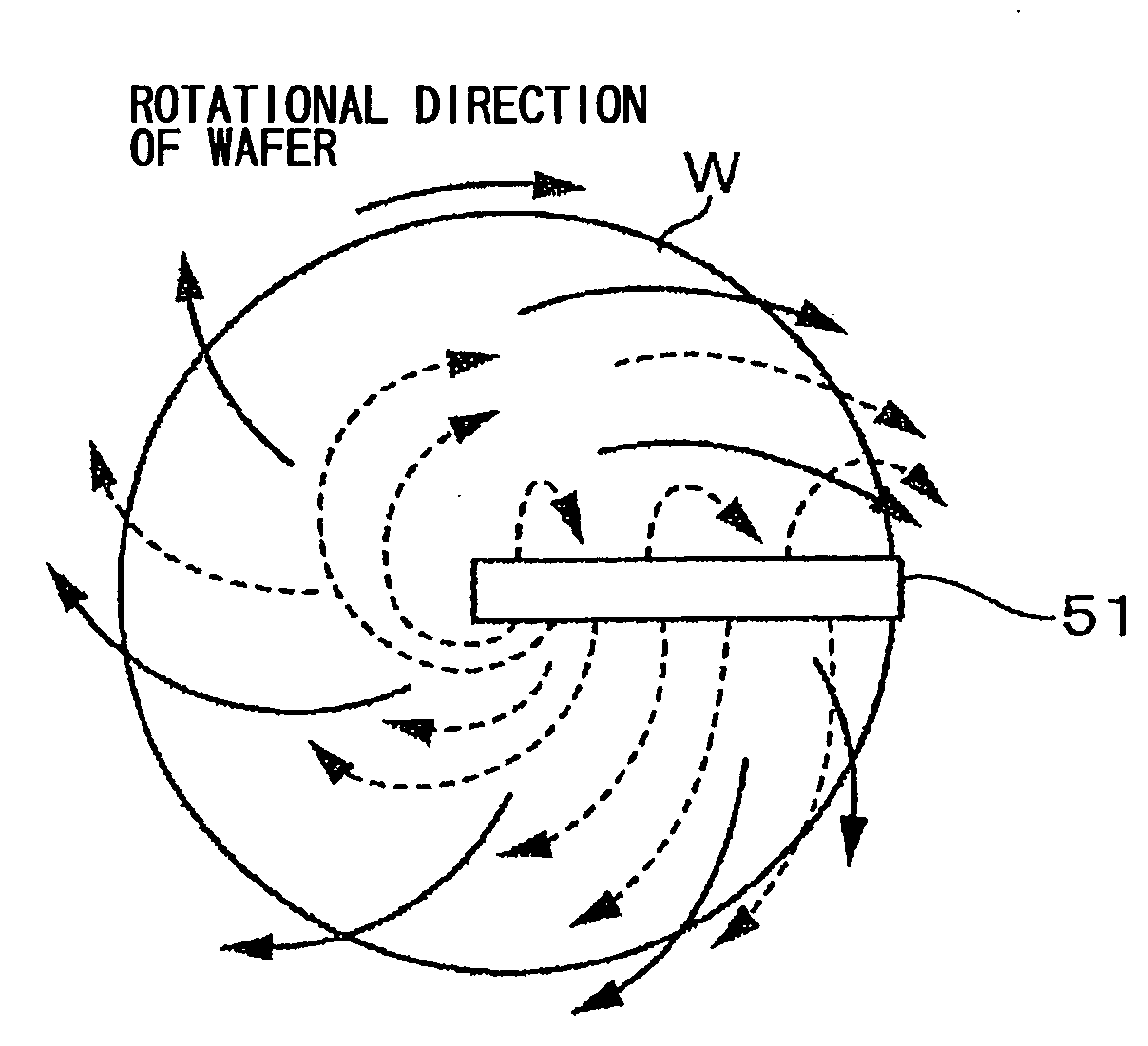
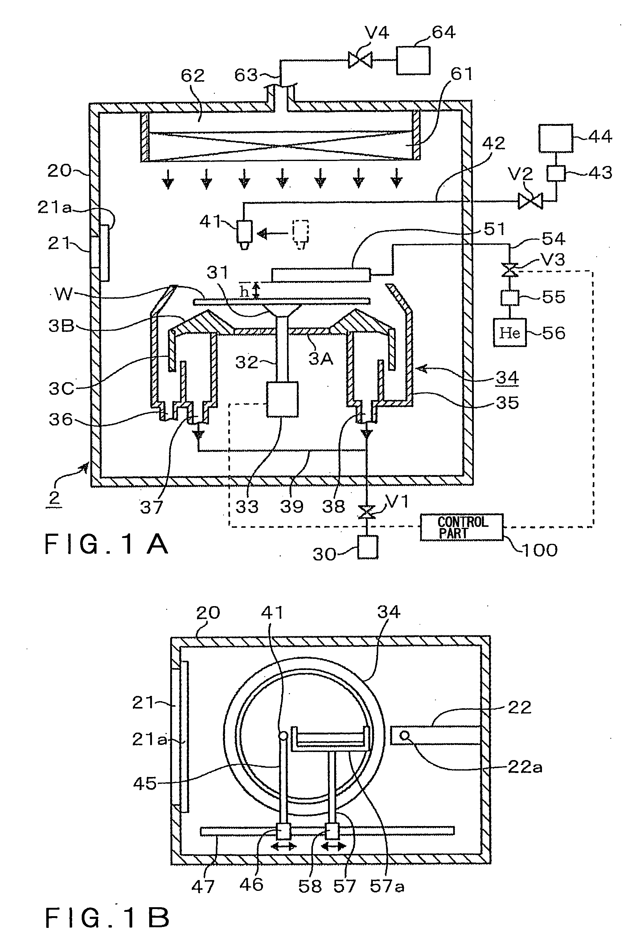
[0024]According to the above invention, when the surface of the substrate, which has been spin-coated with the chemical, is spin-dried, while forming the down flow of the atmospheric gas, by supplying the laminar-flow-forming gas having a coefficient of kinematic viscosity larger than that of the atmospheric gas, the laminar-flow-forming gas is mixed into the gas flow of the atmospheric gas spreading outward along the surface of the substrate. Thus, the coefficient of kinematic viscosity of the gas flow formed on the surface of the substrate is increased. Since a radius of a laminar flow to be formed on the surface of the substrate is in proportion to the coefficient of kinematic viscosity of the gas, a laminar-flow area on the surface of the substrate is widened. Thus, generation of windmill-like tracks on the surface of the substrate can be restrained to thereby perform an improved coating process.
[0025]In addition, since the supply of the laminar-flow-forming gas to the surface of the substrate is performed by the nozzle, the consumption of the laminar-flow-forming gas can be reduced, as compared with an art for replacing the whole atmosphere, in which the substrate is placed, with the laminar-flow-forming gas, and thus a long time period for replacing the gas can be saved. In addition, since the substrate is located in the down flow of the atmosphere, and the atmosphere is discharged from around the substrate, there can be eliminated the problem associated with a method in which a lid is provided above the substrate to form a closed space. Namely, there is no possibility that mist scattered form the substrate adheres to the lid and becomes particles.

Problems solved by technology

However, when a resist liquid is applied to a large wafer, such as a 12-inch wafer, an increase in the rotational speed of the wafer may invite, as shown in FIG. 25A, formation of about 30 wrinkles on a surface of the coated resist in an area close to the peripheral edge of the wafer, which makes non-uniform the film thickness.
As a result, the film-thickness of the resist is made non-uniform, and the windmill-like tracks are formed in the circumferential direction of the wafer.
When the resist liquid is exposed to the turbulent flow at the step in which the solvent is evaporated, the solvent on the surface of the resist liquid is evaporated too fast.
That is, a required amount of the He gas throughout the coating process is increased, which results in increase in cost.
Thus, similar to the coating apparatus described in JP5-283331A, a time lag may occur before the mixed gas is fully supplied, and thus an increasing amount of the He gas to be used may increase the cost.
However, such a washing process requires additional cost.
Moreover, since the lid covers the overall surface of the substrate, the aforementioned down flow cannot be formed around the substrate.

Method used


Image

  • Coating Apparatus and Coating Method
  • Coating Apparatus and Coating Method
  • Coating Apparatus and Coating Method

Examples


examples

[0111]In Example 1, there was prepared a coating apparatus in which, in place of a resist, an oil liquid formed by mixing a commercially available liquid ink and a commercially available neutral detergent (trade name: mama lemon) at a ratio of 1:1 was stored in a supply source 44, and the thus formed oil liquid in place of a resist was supplied from a liquid supply nozzle 41 to a wafer W. The other structures of the coating apparatus are the same as those of the aforementioned coating apparatus 2.

[0112]In accordance with the procedure for applying a resist in the aforementioned embodiment, the oil liquid was applied onto a wafer W, and an oil film was formed by the oil liquid.

[0113]As the wafer W, a 300-mm wafer (12-inch wafer) was used (all the wafers W used in the following examples have a diameter of 300 mm). As a gas nozzle for ejecting an He gas, the gas nozzle 65 as shown in FIG. 7A was used. A gas-discharging flow rate in a housing 20 during the coating process of the oil liq...


PUM


Abstract

The invention is a coating apparatus including: a substrate-holding part that holds a substrate horizontally; a chemical nozzle that supplies a chemical to a central portion of the substrate horizontally held by the substrate-holding part; a rotation mechanism that causes the substrate-holding part to rotate in order to spread out the chemical on a surface of the substrate by a centrifugal force, for coating the whole surface with the chemical; a gas-flow-forming unit that forms a down flow of an atmospheric gas on the surface of the substrate horizontally held by the substrate-holding part; a gas-discharging unit that discharges an atmosphere around the substrate; and a gas nozzle that supplies a laminar-flow-forming gas to the surface of the substrate, the laminar-flow-forming gas having a coefficient of kinematic viscosity larger than that of the atmospheric gas; wherein the atmospheric gas or the laminar-flow-forming gas are supplied to the central portion of the substrate.

Description

FIELD OF THE INVENTION[0001]This invention relates to a coating apparatus and a coating method of coating a substrate with a chemical such as a resist.BACKGROUND ART[0002]Conventionally, as a technique of coating a substrate such as a semiconductor wafer (hereinafter, wafer), a glass substrate for a liquid crystal display and a substrate for a color filter, with a chemical, a spin coating method has been widely used in order to make substantially uniform the thickness of a coated film and to make thinner the same.[0003]Given herein as an example to describe the spin coating method is a case where a resist liquid is applied to a wafer. At first, in a chamber including a spin chuck on which a wafer can be placed, air is supplied from an upper part of the chamber, and the air is discharged from a lower part of the chamber. Thus, a down flow of air for preventing scattering of particles is formed in the chamber. Following thereto, a wafer is placed on the spin chuck, and the wafer is ho...

Claims


Application Information

Patent Timeline
IPC IPC(8): B05D3/12B05C5/00
CPCB05C11/06G03F7/162H01L21/67017H01L21/67023H01L21/6715B05D3/0406B05D2203/35B05D3/0486B05D2203/30B05C11/08B05D1/005B05C15/00
Inventor SAWADA, IKUOMATSUZAKI, KAZUYOSHITANAKA, TAKASHIIWASHITA, MITSUAKIMUNAKATA, MIZUE
Owner TOKYO ELECTRON LTD
Why Eureka
Eureka Blog
Learn More