
Parallel signal processing system and method

a signal processing and parallel processing technology, applied in the field of real-time digital audio processing, can solve the problems of serial execution tasks and low efficiency, and achieve the effect of efficiently exploiting the processing power and parallelism of a massively parallel processor

Active Publication Date: 2009-06-18
PATENT ARMORY INC
View PDF2 Cites 20 Cited by
  • Summary
  • Abstract
  • Description
  • Claims
  • Application Information

AI Technical Summary

Benefits of technology

[0027]The present system and method improve the cost and efficiency of real time digital signal processing with respect to analog signals, and in particular, telephony signaling functions.
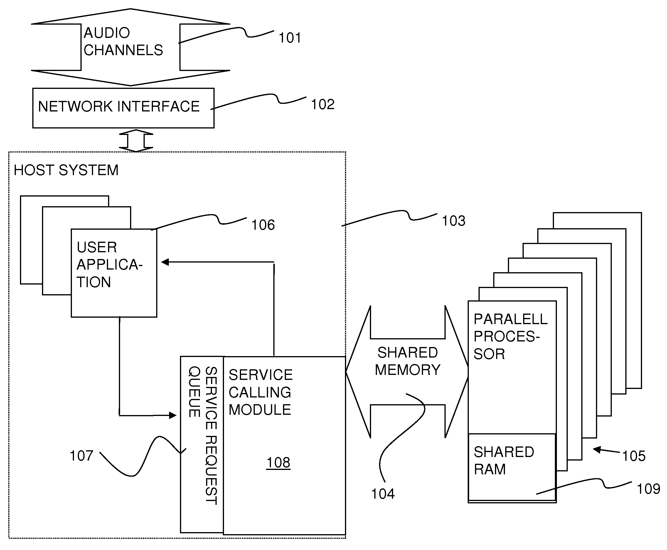
[0028]In one aspect of the invention, a massively parallel digital signal processor is employed to perform telephony in-band signaling detection and analysis. In another aspect, a massively parallel coprocessor card is added to a telephony server which is executed on a standard processor to increase call progress tone detection performance. Advantageously, the massively parallel processor is adapted to execute standard software, such as C language, and therefore may perform both massively parallel tasks, and with a likely lower degree of efficiency, serial execution tasks as well. Thus, a telephony system may be implemented on a single processor system, or within a distributed and / or processor / coprocessor architecture.
[0029]Data blocks, each including a time slice from a single audio channel, are fed in parallel to the massively parallel processor, which performs operations in parallel on a plurality of time slices, generally executing the same instruction on the plurality of time slices. In this system, real time performance may be effectively achieved, with a predetermined maximum processing latency. In many cases, it is not necessary to detect tones on each audio channel continuously, and therefore the system may sample each channel sequentially. In addition, if a Fast Fourier Transform-type algorithm is employed, the real (I) and imaginary (Q) channels may each be presented with data from different sources, leading to a doubling of capacity. Thus, for example, using an nVidia Tesla™ C870 GPU, with 128 processors, each processor can handle 8 (real only) or 16 (real and imaginary) audio channels, leading to a density of 1024 or 2048 channel call progress tone detection. Practically, the system is not operated at capacity, and therefore up to about 800 voice channels may be processed, using a general purpose commercially available coprocessor card for a PC architecture.
[0031]A particular advantage of this architecture arises from the suitability of the call progress tone analysis to be performed in parallel, since the algorithm is deterministic and has few or no branch points. Thus, the task is defined to efficiently exploit the processing power and parallelism of a massively parallel processor.

Problems solved by technology

Advantageously, the massively parallel processor is adapted to execute standard software, such as C language, and therefore may perform both massively parallel tasks, and with a likely lower degree of efficiency, serial execution tasks as well.

Method used


Image

  • Parallel signal processing system and method
  • Parallel signal processing system and method
  • Parallel signal processing system and method

Examples


embodiment # 1

Embodiment #1

[0058]The present example provides computer executable code, which is stored in a computer readable medium, for execution on a programmable processor, to implement an embodiment of the invention. The computer is, for example, an Intel dual core processor based machine, with one or more nVidia Tesla® compatible cards in PCIe x16 slots, for example, nVidia C870 or C1060 processor. The system typically stores executable code on a SATA-300 interface rotating magnetic storage media, i.e., a so-called hard disk drive, though other memory media, such as optical media, solid state storage, or other known computer readable media may be employed. Indeed, the instructions may be provided to the processors as electromagnetic signals communicated through a vacuum or conductive or dielectric medium. The nVidia processor typically relies on DDR3 memory, while the main processor typically relies on DDR2 memory, though the type of random access memory is non-critical. The telephony sign...

embodiment # 2

Embodiment #2

[0064]The second embodiment may employ similar hardware to the first embodiment.

/ / This embodiment is slower, but also uses less memory than embodiment #1 above Data structures to be used by module 108

RQueueType Structure   / / Job Request Queue  ServiceType  ChannelID / / Channel Identifier  VoiceData / / Input Data  Output / / Output DataEnd Structure / / This embodiment uses a single queue, but stores other data in a / / temporary queue when the single queue is not available. This isless memory intensive, but slower.RQueueType RQueue[200]  / / Maximum of 200 Requests

[0065]Procedures to be Used by Module 108

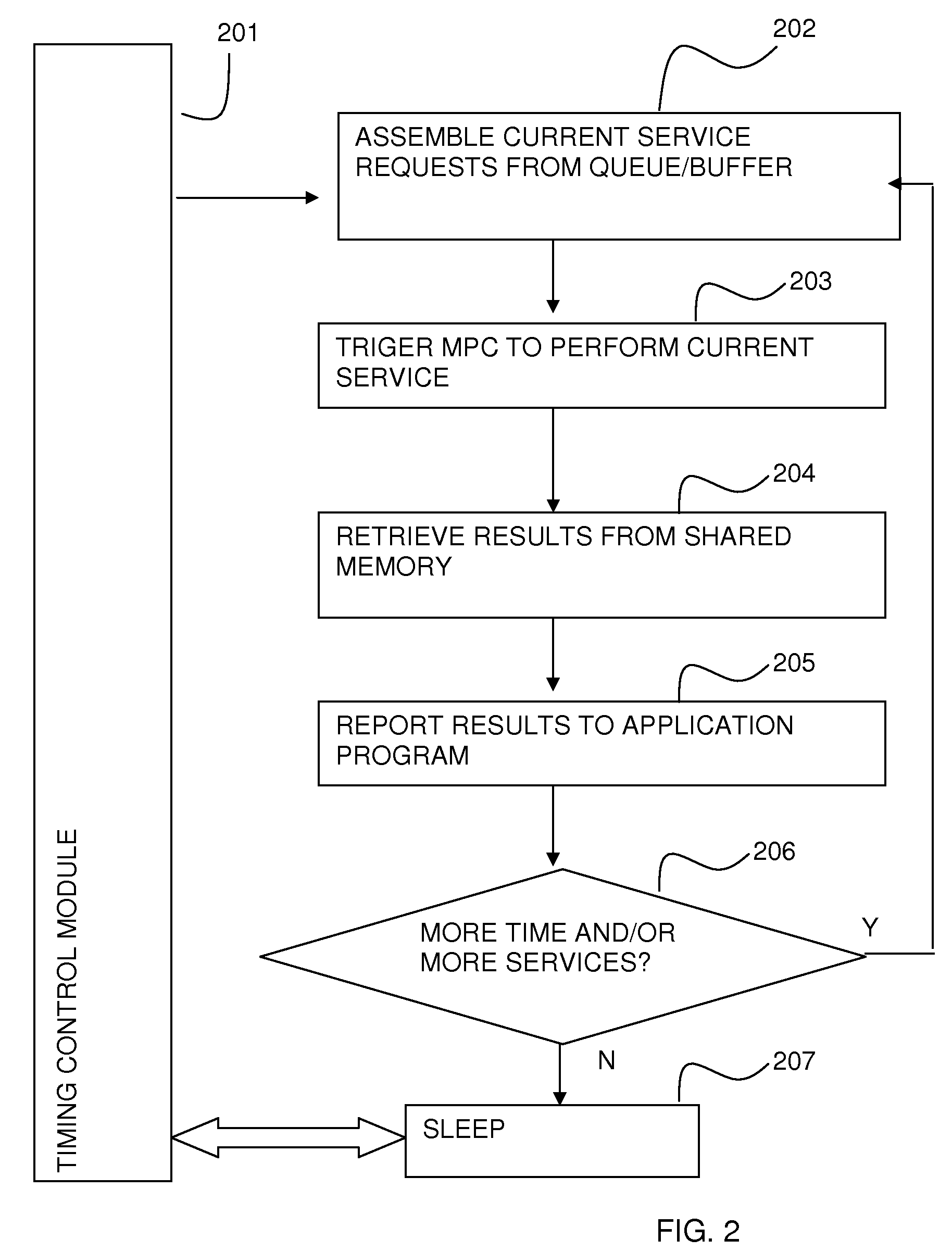
/ / Initialization FunctionInit:Initialize Request QueueInitialize Service EntryStart Service Poll Loop / / Service Request FunctionReqS:Lock RQueueInsert Service Information into RQueueUnlock RQueueWait for completion of ServiceReturn output / / Service Poll Loop / / to run continuouslySerPL: Get timestamp and store in St   / / Let's do FFT / FHT  For all element in RQueue where SerivceTyp...


PUM


Abstract

A system and method for processing a plurality of channels, for example audio channels, in parallel is provided. For example, a plurality of telephony channels are processed in order to detect and respond to call progress tones. The channels may be processed according to a common transform algorithm. Advantageously, a massively parallel architecture is employed, in which operations on many channels are synchronized, to achieve a high efficiency parallel processing environment. The parallel processor may be situated on a data bus, separate from a main general purpose processor, or integrated with the processor in a common board or integrated device. All, or a portion of a speech processing algorithm may also be performed in a massively parallel manner.

Description

BACKGROUND[0001]1. Field of the Invention[0002]The invention relates to the field of real time digital audio processing, particularly in a telephony switch context.[0003]2. Background of the invention[0004]Existing telephone systems, such as the Calltrol Object Telephony Server (OTS™), tend to require relatively expensive special purpose hardware to process hundreds of voice channels simultaneously. More information about this system can be found at www.calltrol.com / newsolutionsforoldchallenges.pdf, www.calltrol.com / crmconvergence_saleslogix.pdf, and www.calltrol.com / CalltrolSDKWhitepaper6-02.pdf, each of which is expressly incorporated herein by reference in its entirety.[0005]In many traditional systems, a single dedicated analog or digital circuit is provided for each public switch telephone network (PSTN) line. See, e.g., Consumer Microcircuits Limited CMX673 datasheet, Clare M-985-01 datasheet. In other types of systems, the call progress tone analyzer may be statistically shar...

Claims


Application Information

Patent Timeline
Patent Type & Authority Applications(United States)
IPC IPC(8): H04M1/00
CPCG10L15/34H04M7/129H04M19/02G10L25/18G10L25/21G10L25/27
Inventor WU, WAI
Owner PATENT ARMORY INC
Learn More