
Guided transport of magnetically labeled biological molecules and cells

a technology of biological molecules and magnetic labels, applied in the direction of high-speed magnetic separators, solid separation, chemistry apparatus and processes, etc., can solve the problems of inability to separate each individual label or molecule, the new method is theoretically slower, and the overall oriented extraction technique is incapable of producing single-molecule detections, etc., to achieve better signal-to-background noise ratio, reduce the complexity of biological preparation, and eliminate diffraction effects and strong background noise

Active Publication Date: 2009-06-04
HEADWAY TECH INC
View PDF11 Cites 15 Cited by
  • Summary
  • Abstract
  • Description
  • Claims
  • Application Information

AI Technical Summary

Benefits of technology

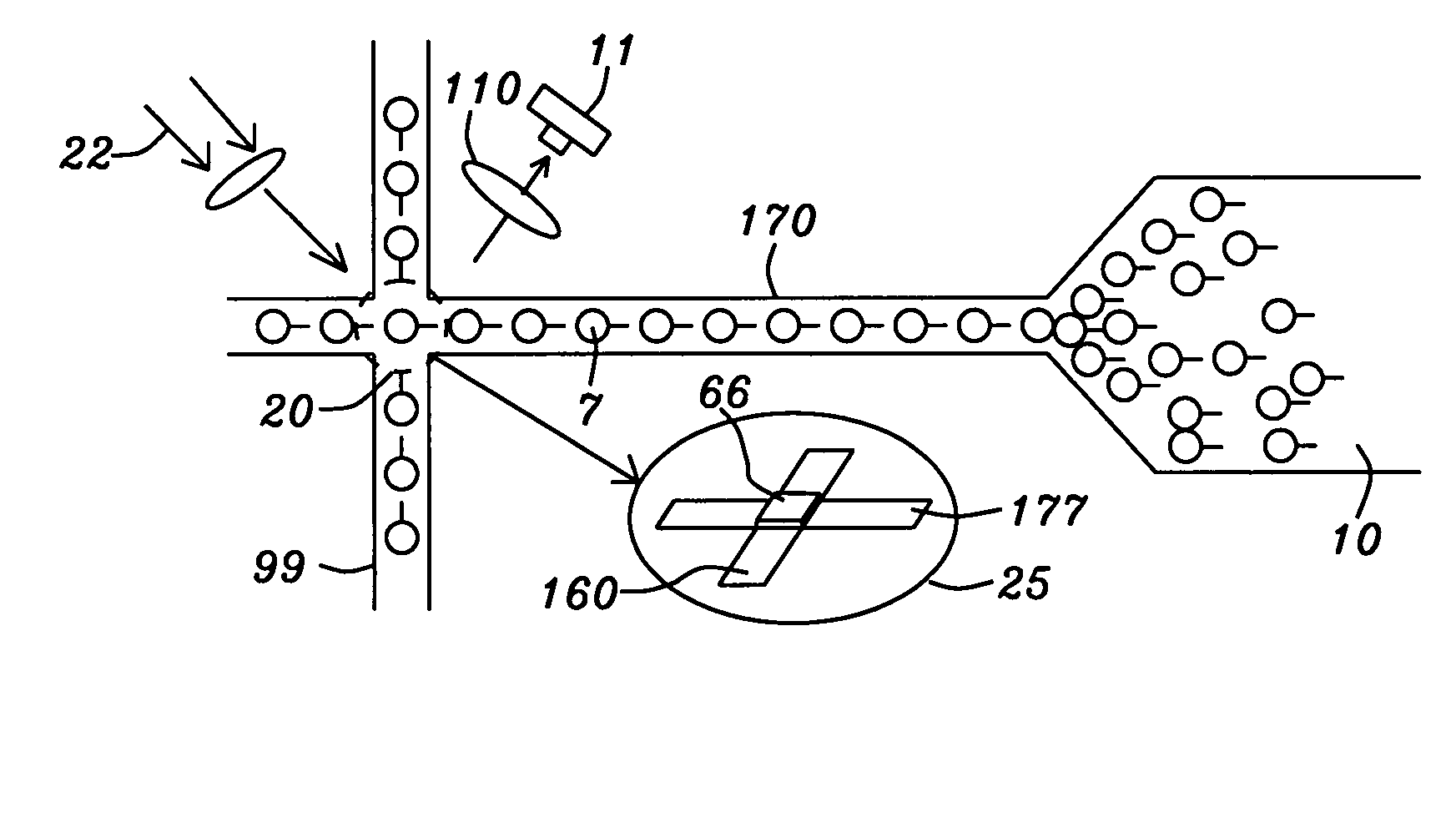
The patent describes a method for detecting small magnetic particles that act as labels attached to biological molecules or cells. The method uses an array of patterned magnetic devices or strips that can guide and transport the magnetic labels to a specific position for optical detection. The magnetic labels can be attached to the molecules or cells using a one-step incubation process, which simplifies the preparation of the biological solution. The method can detect the magnetic labels and cells in a solution and extract them for optical detection without the disadvantageous effects of optical diffraction. The use of patterned magnetic devices or strips makes the detection process easier and faster.

Problems solved by technology

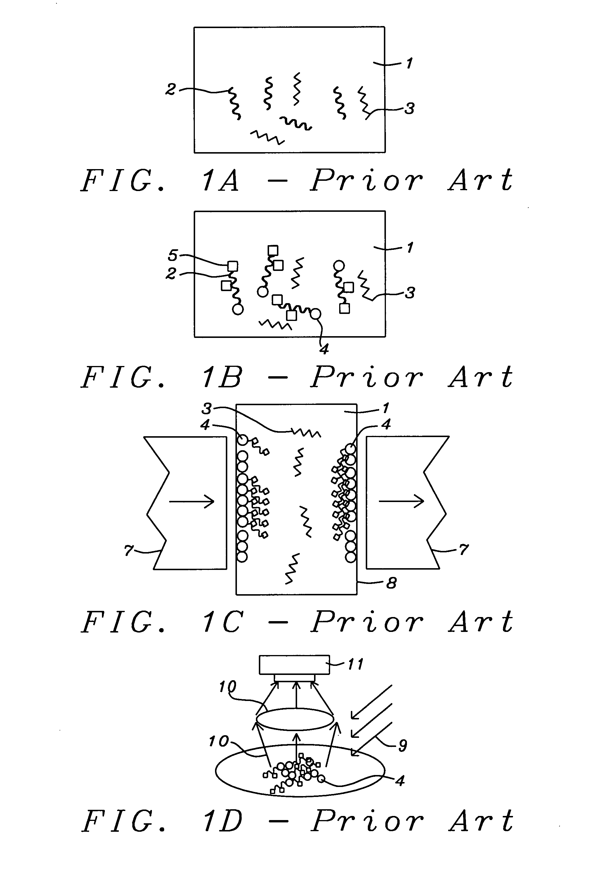
However, such an ensemble oriented extraction technique is incapable of producing detections at the single molecule level, because the target molecules are detected in the form of concentrated clusters or as droplets where signal scattering by unbound labels or liquid solution can be very high.
Since label binding to molecule and molecule binding to surface requires two separate incubation processes, this new method is theoretically slower than the conventional optical method in its preparation step, because in the optical identification method a single incubation is enough to accomplish both magnetic label attachment and dye attachment to the target molecules.
The conventional ensemble magnetic label extraction and optical detection scheme illustrated in FIG. 1A-1D will not be able to separate each individual label or molecule, even using state-of-the-art flow-cytometry or micro-fluidics systems.
None of them provide a robust method of reliably detecting the presence of individual beads.

Method used


Image

  • Guided transport of magnetically labeled biological molecules and cells
  • Guided transport of magnetically labeled biological molecules and cells
  • Guided transport of magnetically labeled biological molecules and cells

Examples


embodiment 1a

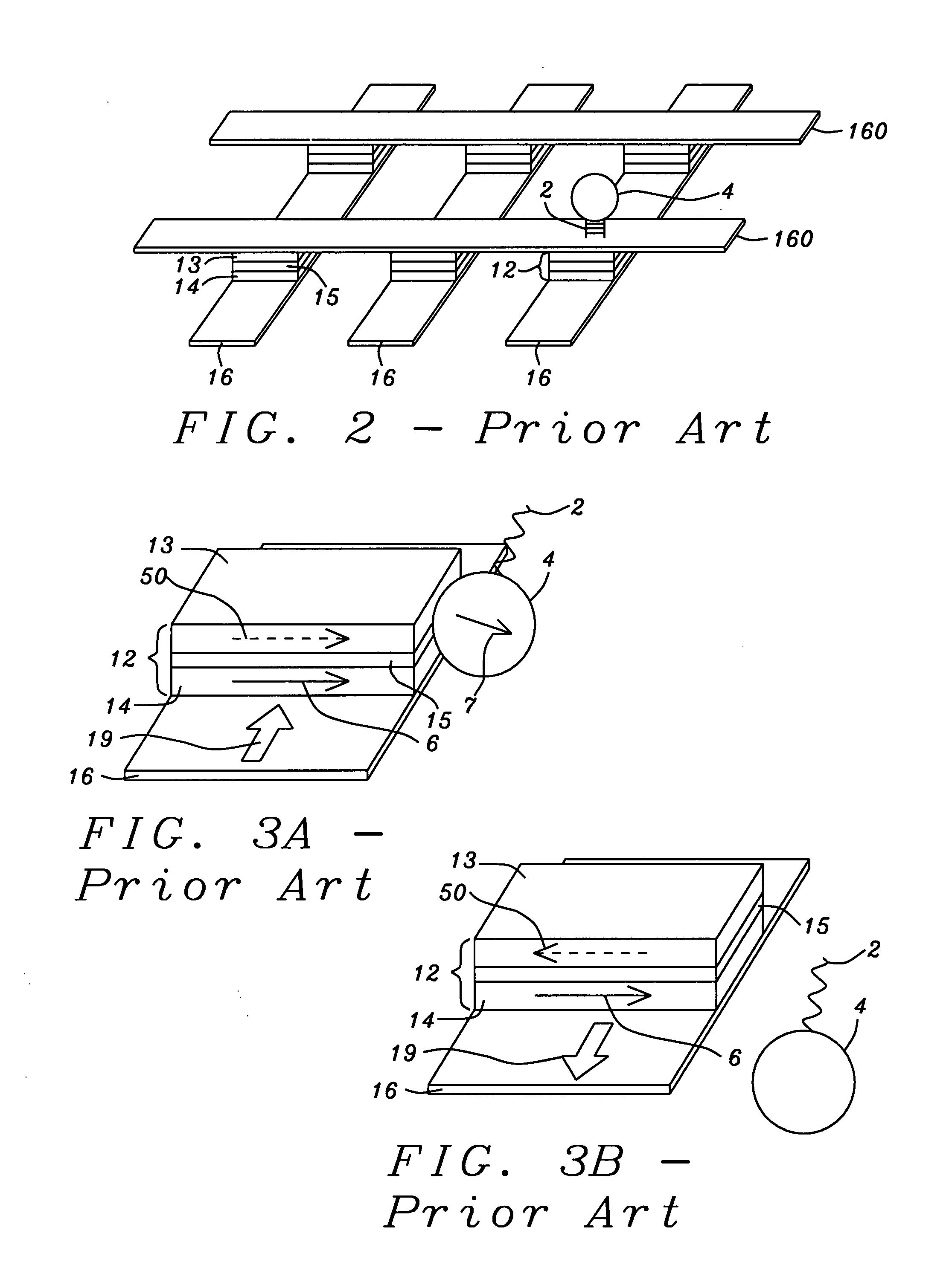
[0086]The trapping structure (also denoted a “device”), shown schematically in FIG. 12A, is formed beneath a protection layer that is not shown here. The term“trapping” as used herein refers to the capture and holding of a magnetized label in a substantially fixed position.

[0087]The magnetic labels are attracted by the magnetic fields of the trapping structure and they move against the protection layer's top surface which can be the bottom surface of a confinement device as will be illustrated below. The labels are transported along the top of the protection layer along a Direction 2 as indicated on the Cartesian coordinate system in the figure. The trapping structure is a multilayered device that includes four parts, a magnetic free layer (13), a non-magnetic spacer layer (15), a magnetic pinned layer (14) and a current conduction path (16) that can carry current (19) in either direction along Direction 1 as shown by the double-headed arrow. Free layer (13) magnetization can be in ...

embodiment 1b

[0090]Referring to FIG. 12B, there is shown schematically a device that is the same as that in FIG. 12A except that the adjacent current carrying line ((16) in FIG. 12A) is absent and the current (19) is carried by the interlayer (15).

embodiment 1c

[0091]Referring to FIG. 12C, there is again shown schematically a trapping structure that would be formed beneath a protection layer. The magnetic labels would be attracted against the protective layer by the trapping structure beneath the layer. The trapping structure includes two parts, a single magnetic layer (13) and a current conduction path (16). The natural or normal magnetization of layer (13) is maintained by an internal field along the in-plane Direction 1 that is perpendicular to Direction 2. The internal field of layer (13) can be from any one of, or a combination of crystalline anisotropy, shape anisotropy and stress-induced anisotropy. The internal field in layer (13) can also be due to an exchange coupling with an adjacent antiferromagnetic layer (not shown) or from a SAF structure (not shown) as discussed above. Electric current (19) flows within current carrying layer (16) along Direction 1 and generates a magnetic field to induce a Direction 2 magnetization compone...


PUM


Abstract

Presented herein is a method and devices for identifying biological molecules and cells labeled by small magnetic particles and by optically active dyes. The labeled molecules are typically presented in a biological fluid but are then magnetically guided into narrow channels by a sequential process of magnetically trapping and releasing the magnetic labels that is implemented by sequential synchronized reversing the magnetic fields of a regular array of patterned magnetic devices that exert forces on the magnetic particles. These devices, which may be bonded to a substrate, can be formed as parallel magnetic strips adjacent to current carrying lines or can be substantially of identical structure to trilayered MTJ cells. Once the magnetically labeled molecules have been guided into the appropriate channels, their optical labels can be detected by a process of optical excitation and de-excitation. The molecules are thereby identified and counted.

Description

BACKGROUND OF THE INVENTION[0001]1. Field of the Invention[0002]This invention relates to the guided transport of biological molecules or cells to which small magnetic particles have been attached, particularly when such molecules or cells are then to be detected optically in a chemical or biological assay.[0003]2. Description of the Related Art[0004]Physical extraction of biological cells and molecules from liquid biological solutions by exerting magnetic forces on attached magnetic labels (i.e., small magnetized particles) has been a widely adopted technique in medical and biological practice. The biological cells or molecules have magnetic labels attached to them, the labels being very small particles of magnetic material that are magnetizable by an external magnetic field. Such small particles of magnetic material are typically superparamagnetic, meaning that thermal effects are sufficiently large to destroy spontaneous domain formation and, therefore, they must be placed in an ...

Claims


Application Information

Patent Timeline
Patent Type & Authority Applications(United States)
IPC IPC(8): B03C1/02
CPCB03C1/033B03C1/034B03C2201/26B03C2201/18B03C1/288
Inventor ZHOU, YUCHENGUO, YIMIN
Owner HEADWAY TECH INC
Learn More