
Float glass for display substrate and method for producing it

a technology of substrate glass and floating glass, which is applied in the direction of glass rolling apparatus, glass making apparatus, manufacturing tools, etc., can solve the problems of unstable production, affecting the life span of production apparatuses, and asymmetrical substrate glass at anterior and posterior, so as to reduce the temperature of each step carried out for producing substrate glass, the effect of stable production and low viscosity

Inactive Publication Date: 2009-05-28
ASAHI GLASS CO LTD
View PDF3 Cites 19 Cited by
  • Summary
  • Abstract
  • Description
  • Claims
  • Application Information

AI Technical Summary

Benefits of technology

[0020]The substrate glass of the present invention has a low viscosity at a high temperature while securing properties required for a glass for a display substrate, particularly properties required for a glass for a PDP substrate. Therefore, the temperature of each step carried out for producing the substrate glass can be lowered. Namely, the temperature of the melting step, the temperature of the clarification step and the temperature of the forming step (for example, a forming step in a float process) can be lowered.
[0021]By lowering the temperature of each step carried out for producing the substrate glass, it is possible to obtain advantages such that production becomes stable, the life span of production apparatus is extended, and the production cost of the substrate glass becomes low.
[0022]Further, by lowering the temperature of each step carried out for producing the substrate glass, it is possible to obtain the following advantages which relate to properties of the substrate glass.
[0023]By lowering the temperature at the forming step in the float process, tin defects in a substrate glass to be obtained can be reduced. If the temperature in the forming step of the float process is high, an amount of molten tin to evaporate in a float bath increases. Evaporated tin is condensed in the vicinity of the ceiling of the float bath and drops on glass ribbons, and tin defects result.
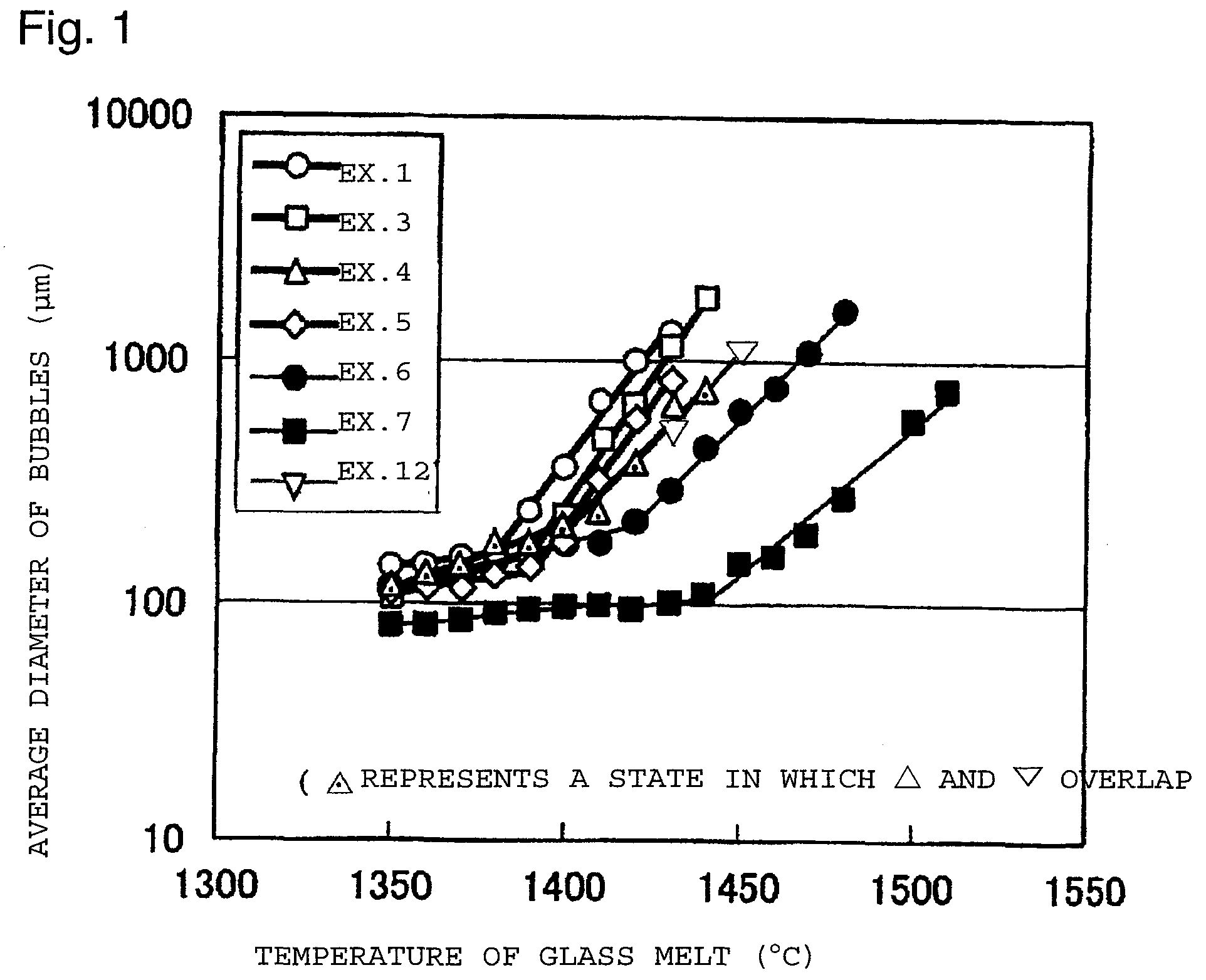
[0024]Further, in the substrate glass of the present invention, even if the temperature in the clarification step is lowered, the effect of the clarifier can be preferably elicited. As a result, it is possible to obtain a high quality substrate glass having little foam.

Problems solved by technology

Particularly, in a case where a continuous furnace such as a belt furnace, of which productivity is high, is used, there is a problem that due to the temperature difference between the anterior and the posterior of the substrate glass, a dimensional change results such that the substrate glass becomes asymmetrical at anterior and posterior.
Therefore, it is required to increase the temperature at each step carried out for producing a substrate glass, namely it is required to increase the glass melting temperature, the glass clarification temperature and the glass forming temperature, and problems result such that stable production is difficult, life span of production apparatuses is harmed, and production cost of a substrate glass is high.
However, in the case of the glass composition, of which the high temperature viscosity is simply lowered, properties required for the substrate glass for PDP cannot be satisfied.
Namely, properties such as the specific gravity of the substrate glass, the glass transition temperature, chemical resistance, dielectric constant, volume resistivity, reflectance, thermal expansion coefficient and distortion point cannot be satisfied within the range required for the substrate glass for PDP.
Further, in the case of the glass composition, of which the high temperature viscosity is simply lowered, the temperature of each step carried out for producing the substrate glass can be thereby lowered, however, if the temperature at the clarification step is lowered, the effect of a clarifier deteriorates.
However, if the temperature at the clarification step is lowered in accordance with the composition, of which the high temperature viscosity is lowered, SO3 is not likely to decompose in molten glass, and the effect of the clarifier deteriorates.

Method used


Image

  • Float glass for display substrate and method for producing it

Examples


examples

[0093]Now, the present invention will be described in further detail with reference to Examples. However, the present invention is by no means restricted to such specific Examples.

[0094]Table 1 shows glass compositions (mass %) of Examples 1 to 5 (Examples of the present invention), Table 2 shows glass compositions of Examples 6 to 11 (Comparative Examples), and Table 3 shows glass compositions of Examples 12 to 16 (Examples of the present invention).

[0095]Materials of respective components were prepared so as to be the desired composition, and heated and melted in a platinum crucible at a temperature of from 1,500 to 1,600° C. for 4 hours. At the time of melting the glass, a platinum stirrer was inserted, and the molten glass was stirred for 2 hours to homogenize the glass. Then, the glass melt was cast, annealed and then polished to obtain a glass plate having a thickness of 2.8 mm.

[0096]With respect to the glass thus obtained, the glass composition (unit: mass %), the thermal exp...


PUM

PropertyMeasurementUnit
glass transition temperatureaaaaaaaaaa
viscosityaaaaaaaaaa

Abstract

To provide a float glass for a display substrate, of which the high temperature viscosity is low, without impairing properties for a substrate glass for a display.A float glass for a display substrate, characterized in that its composition consists essentially of, as represented by mass % based on oxide, from 52 to 62% of SiO2, from 5 to 15% of Al2O3, from more than 0% to 9% of MgO, from 3 to 12% of CaO, from 9 to 18% of SrO, from 0 to 13% of BaO, from 25 to 30% of MgO+CaO+SrO+BaO, from 6 to 14% of Na2O+K2O+Li2O, from 0 to 6% of ZrO2 and from 0 to 1% of SO3, the temperature of glass melt corresponding to the viscosity of 102 dPa·s is at most 1,520° C., the temperature of glass melt corresponding to the viscosity of 104 dPa·s is at most 1,120° C., the glass transition temperature is at least 610° C., and the specific gravity is at most 2.9.

Description

TECHNICAL FIELD[0001]The present invention relates to a glass for a display substrate, particularly a float glass which is preferred as a glass for a plasma display panel (hereinafter referred to as PDP) substrate and a method for producing the float glass.BACKGROUND ART[0002]Heretofore, PDP is generally produced by firing metal electrodes, an insulating paste, a rib paste, etc. on a substrate glass at a temperature of from about 550 to 600° C., followed by frit sealing opposed plates and its vicinity. Heretofore, in general soda lime silica glass which is widely used for buildings and automobiles has been used as a glass for a PDP substrate.[0003]However, since the glass transition temperature of the soda lime silica glass is from 530 to 560° C., if the glass is heat-treated at the above firing temperature, the substrate glass deforms or shrinks, and the dimension remarkably changes. Therefore, it has been desired to realize positioning opposed plates and electrodes accurately. Par...

Claims


Application Information

Patent Timeline
Patent Type & Authority Applications(United States)
IPC IPC(8): C03C3/087C03B18/02H01J17/16H01J17/49
CPCC03C3/087H01J11/34H01J11/10
Inventor NAGAI, KENSUKENAKASHIMA, TETSUYAMAEDA, KEI
Owner ASAHI GLASS CO LTD
Learn More