
Electric steering system

a steering system and steering shaft technology, applied in the direction of electronic commutators, dynamo-electric converter control, instruments, etc., can solve the problems of inability to distinguish n and s poles, unnecessary torque generated in brushless motors, and driver discomfort, so as to improve responsiveness and detect steering torque with high sensitivity

Active Publication Date: 2009-05-21
HONDA MOTOR CO LTD
View PDF8 Cites 21 Cited by
  • Summary
  • Abstract
  • Description
  • Claims
  • Application Information

AI Technical Summary

Benefits of technology

[0015]With the electric steering system according to the present invention, it is determined whether or not the estimated rotary angle is appropriate based on the steering torque detected by the torque detection unit provided in the electric steering system in a state where the brushless motor is controlled to be driven by the predetermined current in accordance with the estimate rotary angle. Then, the brushless motor is started on the basis of the estimated rotary angle which is determined to be appropriate. For this reason, since it is possible to prevent a complex process for estimating the rotary angle of the brushless motor, it is possible to reduce a time necessary for estimating the rotary angle and to improve responsiveness upon starting the brushless motor. Also, since it is possible to appropriately assist a driver's steering input by means of the steering assisting force generated by the brushless motor, it is possible to prevent a case in which a driver feels discomfort when steering. Additionally, it is determined whether or not the estimated rotary angle is appropriate based on the steering torque detected by the steering torque detection unit provided in the electric steering system. For this reason, it is possible to prevent a complex configuration of the apparatus without, for example, requiring a new component to be configured.
[0017]In this case, it is possible to prevent a case in which a driver feels discomfort when steering due to an unnecessary excessive torque exceeding a predetermined torque upon controlling the brushless motor by using a predetermined current in accordance with the estimated rotary angle.
[0019]In this case, since the magnetostrictive torque sensor has rigidity relatively larger than that of, for example, a torque sensor for detecting torsion of a torsion bar connecting an input side to an output side of a steering shaft, it is possible to improve responsiveness with respect to the steering torque variation. For this reason, even when the brushless motor is controlled to be driven by the predetermined current, it is possible to detect the steering torque with high sensitivity without a delay. Accordingly, it is possible to reliably carry out a process for determining whether or not the estimated rotary angle is appropriately selected in a short time. Thus, it is possible to prevent a case in which a driver feels discomfort when steering when an assisting torque is delayed due to a start delay of the brushless motor.

Problems solved by technology

However, it is not possible to distinguish N and S poles by observing the inductance variation.
However, in the above-described method according to an example of the related art (Non-Patent Document 2), since a large current saturating the magnetic circuit is excessively supplied in order to determine the magnetic pole of the rotor, an unnecessary torque is generated in the brushless motor.
For this reason, in the brushless motor provided in the electric steering system, a problem arises in that a driver feels an discomfort due to unexpected steering torque, vibration, or noise.
From this point, a problem arises in that it is difficult to reduce a time necessary for determining polarity and it is not possible to improve responsiveness upon starting the brushless motor.
In the brushless motor provided in the electric steering system, a steering assisting force generated from the brushless motor cannot appropriately assist a driver's steering input, thereby causing a problem in that a driver feels discomfort.

Method used


Image

  • Electric steering system
  • Electric steering system
  • Electric steering system

Examples


Embodiment Construction

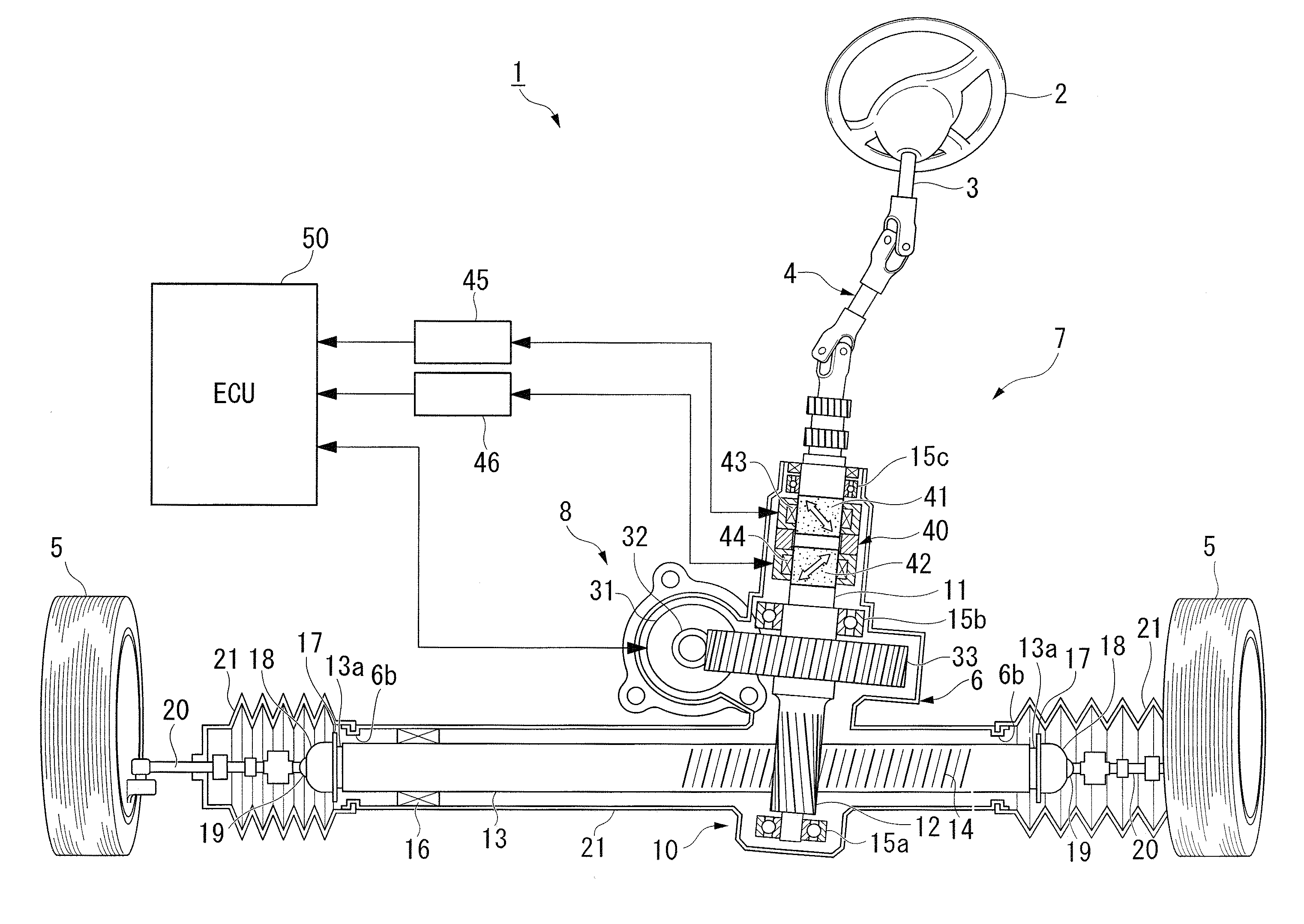
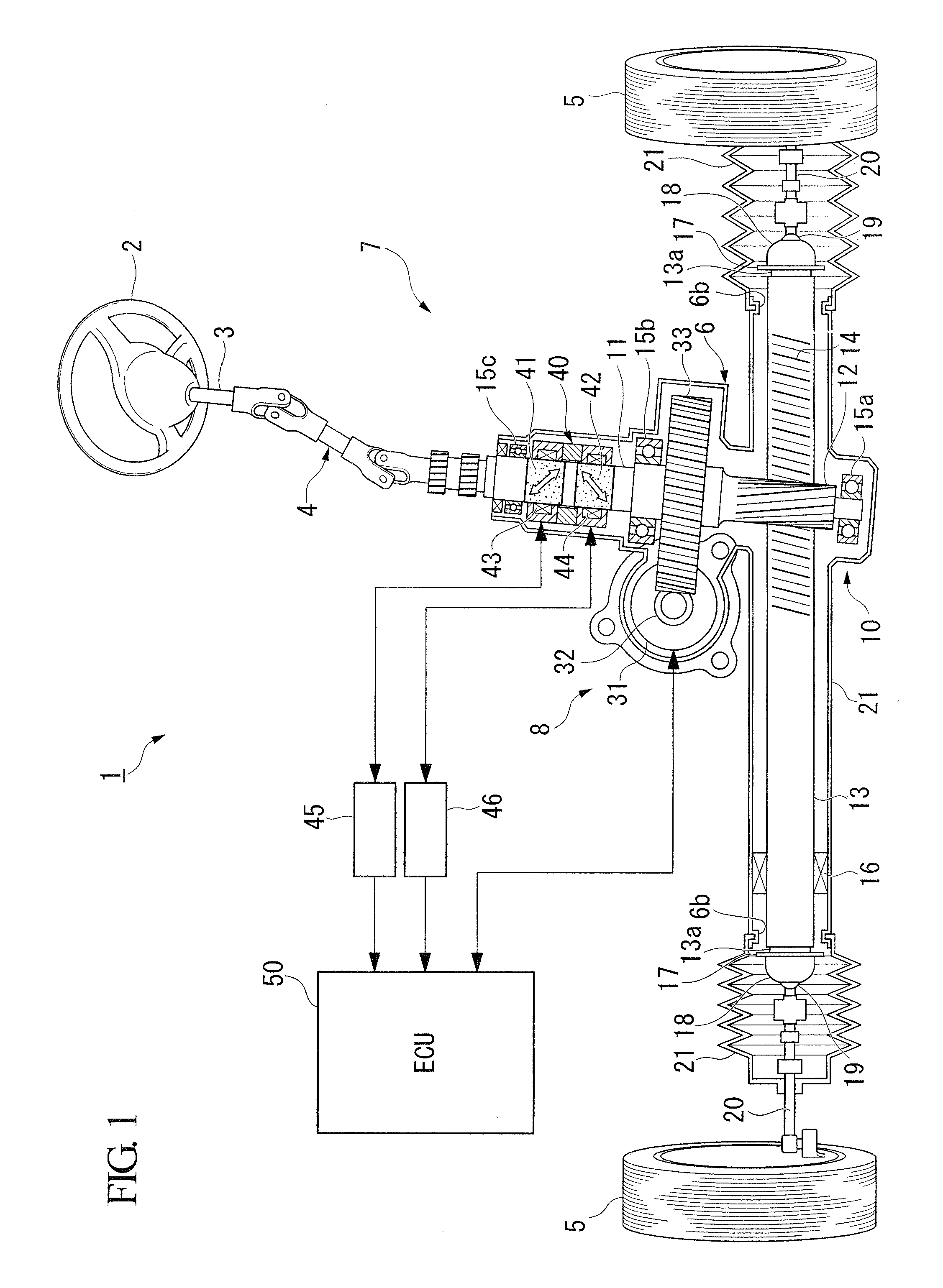
[0036]Hereinafter, an electric steering system according to an embodiment of the present invention will be described with reference to the accompanying drawings.

[0037]For example, as shown in FIG. 1, an electric steering system 1 according to the embodiment includes a steering shaft 3 connected to a vehicle's steering wheel 2, a universal joint 4 connected to the steering shaft 3, a steering mechanism 7 accommodated in a housing 6 constituting a steering gear box, and a steering assisting mechanism 8 for generating a steering assisting force for the steering mechanism 7 in a steering system from the universal joint 4 to wheels 5 and 5.

[0038]The steering mechanism 7 includes a rack and pinion mechanism 10, and a pinion shaft 11 of the rack and pinion mechanism 10 is connected to the universal joint 4.

[0039]A pinion 12 provided in the pinion shaft 11 is engaged to a rack 14 provided in a rack shaft 13 capable of reciprocating in a vehicle width direction.

[0040]For example, the pinion ...


PUM


Abstract

An electric steering system is provided with: a steering torque detection unit which detects a steering torque acting on the shaft; a brushless motor which includes a rotor and a stator having multi-phase stator coils, and generates an assisting torque for assisting the steering torque; a current supply switching unit which drives the brushless motor; a rotary angle estimation unit which outputs an estimated rotary angle; a determination unit which determines whether or not the estimated rotary angle is appropriate by comparison with a direction of the steering torque; and a steering control unit which drives the brushless motor in accordance with the estimated rotary angle determined to be appropriate by the determination unit to control generation of the assisting torque.

Description

[0001]Priority is claimed on Japanese Patent Application No. 2007-302086, filed Nov. 21, 2007, the contents of which are incorporated herein by reference.BACKGROUND OF THE INVENTION[0002]1. Field of the Invention[0003]The present invention relates to an electric steering system.[0004]2. Description of the Related Art[0005]Conventionally, for example, a method which applies a pulse voltage that does not cause a rotation of a rotor to a brushless motor is known when a magnetic-pole rotary angle of the rotor from a magnetic-pole position (i.e., a predetermined reference rotary position) in a stationary state of the brushless motor. In this method, a rotor angle (i.e., the magnetic-pole rotary angle of the rotor from the predetermined reference rotary position) indicating a rotor position is estimated on the basis of a variation in inductance in accordance with a salient-pole property of the rotor based on an inductance obtained by Fourier Transformation from a current and a voltage of ...

Claims


Application Information

Patent Timeline
IPC IPC(8): H02P6/08B62D5/04B62D6/00B62D113/00B62D119/00
CPCB62D5/046H02P21/04H02P6/16
Inventor YONEDA, ATSUHIKOSHIMIZU, YASUOMIYOSHI, TAKASHI
Owner HONDA MOTOR CO LTD
Learn More