Single plate pem fuel cell

Active Publication Date: 2009-05-14
AUDI AG
View PDF4 Cites 2 Cited by
  • Summary
  • Abstract
  • Description
  • Claims
  • Application Information

AI Technical Summary

Benefits of technology

[0006]Objects of the invention include provision of fuel cells: which require a minimal space; which are less expensive than prior art water transport plates; which, although thinner than pairs of prior art water transport plates, are stronger than such pairs; and provision of improved fuel cells and fuel cell power plants. While described in the context of a porous plate technology, this approach may be applied to the use of solid separator plates.
[0007]According to the present invention, a fuel cell has a single porous, at least substantially hydrophilic plate containing both fuel reactant gas flow fields and oxidant reactant gas flow fields, which has wicking strips between every N (where N is an integer between one and several) oxidant and / or fuel reactant gas flow field channels to carry product water away from the cathode, and to provide humidification at the fuel and air inlets through the same porous plate, to assure uniform hydration of the entire planform of the cells.
[0009]The invention is also effective in any embodiment which requires the use of cooler plates disposed between, typically, every two-four fuel cells, such as when long life coolant (e.g., glycol) is used. Where coolant plates are used, the fuel cell stack can become extremely long; use of the present invention allows significant reduction in the size of the fuel cells, thereby reducing the overall stack length.

Problems solved by technology

When a fuel cell power plant is utilized within an electric vehicle, it is subject to being left inoperative in environments which can reach temperatures below the freezing temperature of water.
External water plumbing, pumps, and accumulators are therefore subject to damage from expansion as ice is formed, or otherwise require extensive measures to drain and restore the water, to maintain the temperature above freezing, or to otherwise protect the apparatus from freeze damage.
External water management components, such as pumps and accumulators, add to the weight and take up space.

Method used


Image

  • Single plate pem fuel cell
  • Single plate pem fuel cell
  • Single plate pem fuel cell

Examples


Embodiment Construction

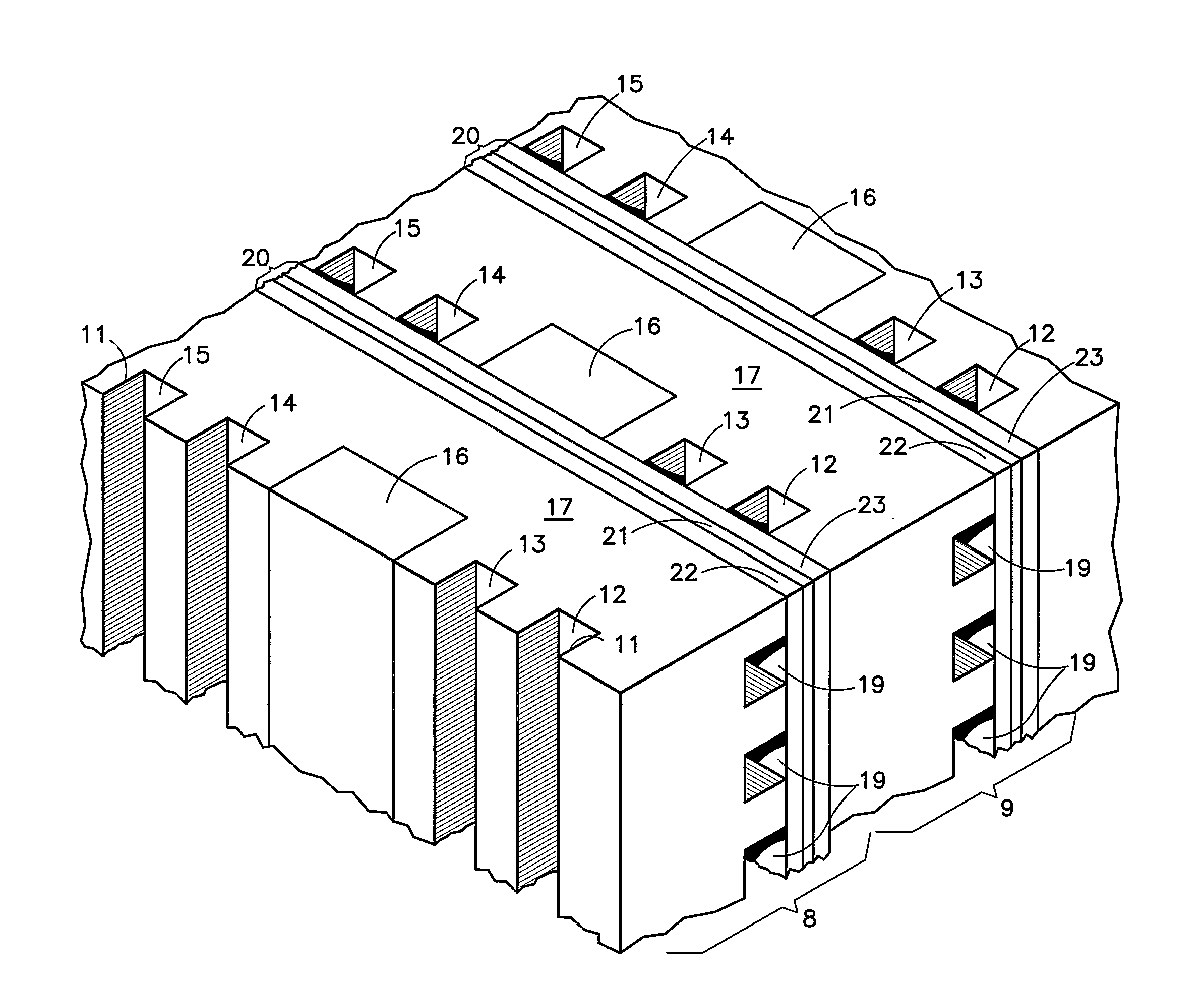
[0018]Referring to FIG. 1, a pair of fuel cells 8, 9 each include a plurality of vertical grooves 11 forming oxidant reactant gas flow field channels 12-15, with an in-cell wicking strip 16 disposed in a slot between the channels 13 and 14, in a conductive, porous, separator plate 17, which is preferably substantially hydrophilic. Each plate 17 has, in this embodiment, horizontal fuel reactant gas flow field channels 19.

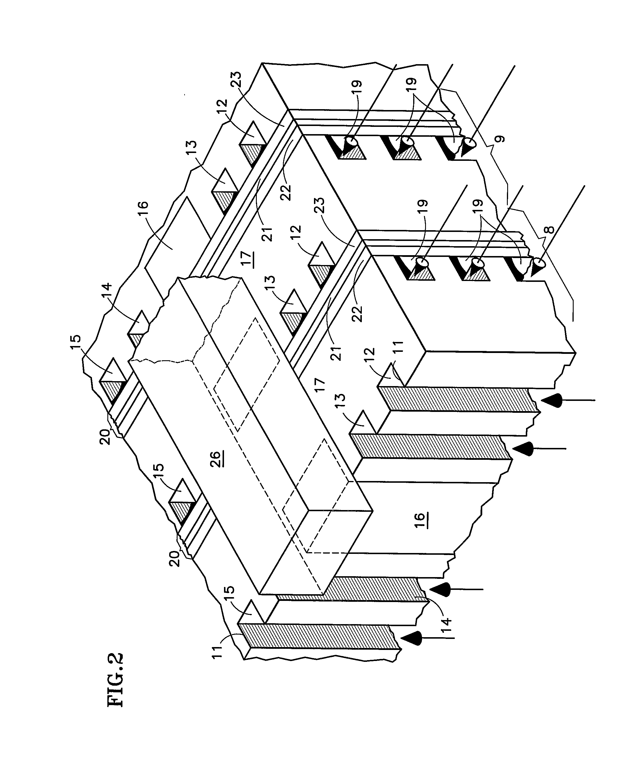
[0019]Each fuel cell 8, 9 also includes, in this embodiment, a unitized electrode assembly 20 which comprises a polymer electrolyte, proton exchange membrane (PEM) 21 with a cathode electrode 22 having a gas diffusion layer (GDL) and an anode electrode 23 having a GDL, with catalyst between the PEM and each GDL. As shown by arrows in FIG. 2, air will flow, in this embodiment, upwardly through the channels 12-15; typically, the fuel will flow from right to left (or vice versa) in half the channels 19 and then flow from left to right (or vice versa) in another half of ...


PUM


Abstract

A fuel cell stack (32) includes a plurality of fuel cells in which each fuel cell is formed between a pair of conductive, porous, substantially hydrophilic plates (17) having oxidant reactant gas flow field channels (12-15) on a first surface and fuel reactant gas flow field channels (19, 19a) on a second surface opposite to the first surface, each ˜f the plates being separated from a plate adjacent thereto by a unitized electrode assembly (20) including a cathode electrode (22), having a gas diffusion layer (GDL) an anode electrode (23) having a GDL with catalyst between each GDL and a membrane (21) disposed therebetween. Above the stack is a condenser (33} having tubes (34) that receive coolant air (39, 40) to condense water vapor out of oxidant exhaust in a chamber (43). Inter-cell wicking strips (26) receive condensate and conduct it along the length of the stack to all cells. In-cell wicking strips (1G. 1˜a) on one or both surfaces conduct the water from the inter-cell wicking strips downwardly along the entire planform of each cell. Reactant air is provided to an air inlet manifold (47) through an air inlet conduit (48) from an air pump (49).

Description

TECHNICAL FIELD[0001]This invention relates to a polymer electrolyte, proton exchange membrane PEM fuel cell having a single separator plate including both fuel reactant gas passages and oxidant reactant gas passages, with water wicking material disposed between some of the reactant gas channels on the same edge of the plate therewith.BACKGROUND ART[0002]In one type of known PEM fuel cell, the reactant gas flow field channels are in “separator” plates (typically called “water transport plates”) which also have water channels in the surface of one or both plates opposite to the reactant gas flow channels. The porous and hydrophilic plates allow product water to migrate from the cathode to the water channels, and allow water to migrate from the water channels to the anode, to assure uniform humidification. Cooling of the fuel cell is typically accomplished with the water in the water channels, which is circulated externally of the fuel cell stack to a heat exchanger that is selectivel...

Claims


Application Information

Patent Timeline
IPC IPC(8): H01M2/38
CPCH01M8/0258H01M8/04164Y02E60/50H01M8/241H01M2008/1095H01M8/04171H01M8/2484H01M8/026
Inventor REISER, CARL A.BALLIET, RYAN J.
Owner AUDI AG
Why Eureka
Try Eureka