
Negative electrode for lithium secondary battery, method for producing same, and lithium secondary battery comprising such negative electrode for lithium secondary battery

a secondary battery and negative electrode technology, applied in the direction of electrochemical generators, cell components, cell component details, etc., can solve the problems of insufficient cycle characteristics, large volumetric change of silicon, and lower current collection ability, and achieve excellent charge-discharge cycle characteristics and high charge-discharge capacity

Active Publication Date: 2009-05-07
PANASONIC CORP
View PDF11 Cites 39 Cited by
  • Summary
  • Abstract
  • Description
  • Claims
  • Application Information

AI Technical Summary

Benefits of technology

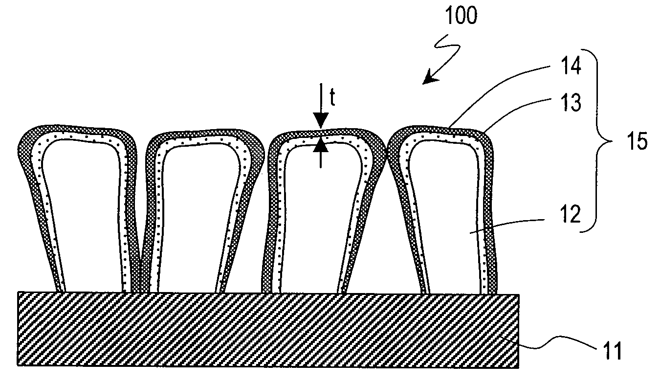
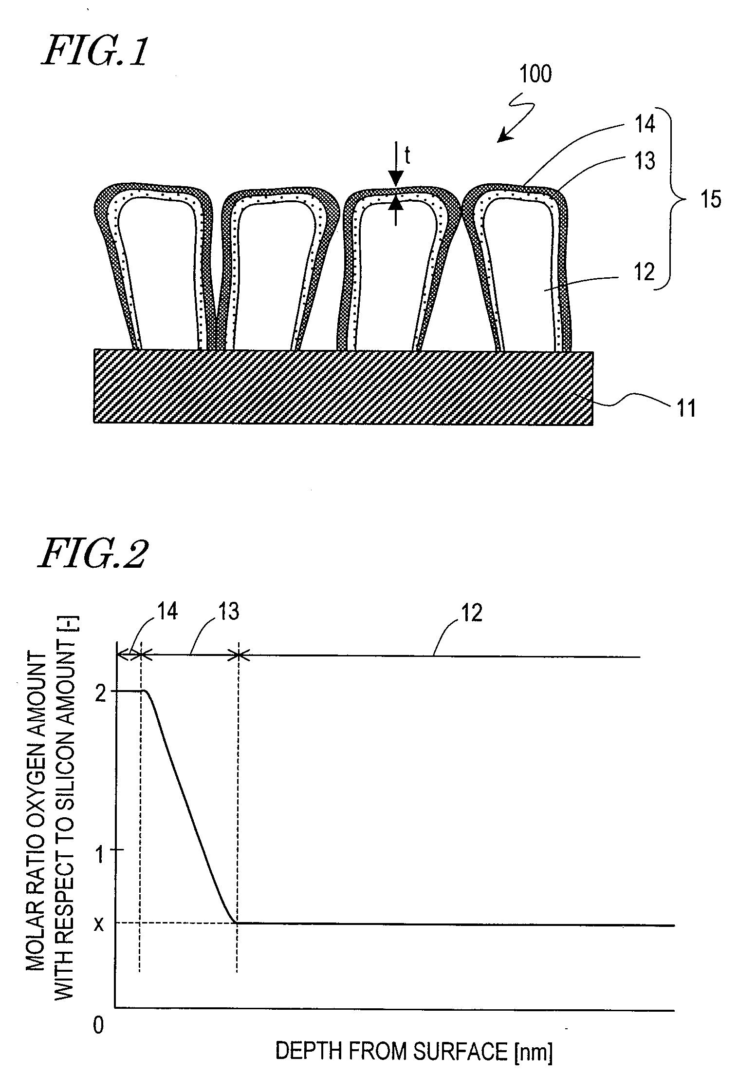
[0013]In accordance with the above construction, a covering layer composed of silicon dioxide is formed on the surface of the negative-electrode active material body, and thus the decomposition reaction of an electrolytic solution occurring when the electrolytic solution comes directly in contact with the negative-electrode active material body can be suppressed. Therefore, any high-resistance coating associated with the decomposition reaction of the electrolytic solution becomes unlikely to be formed on the surface of the negative electrode. As a result, polarization occurring due to such a coating can be minimized, and the charge-discharge cycle characteristics can be improved.
[0015]According to the present invention, in a negative electrode for a lithium-ion secondary battery, decomposition reaction of an electrolytic solution caused by a negative-electrode active material body can be suppressed, while ensuring a high charge-discharge capacity. As a result, a lithium secondary battery having excellent charge-discharge cycle characteristics can be provided.

Problems solved by technology

However, silicon undergoes large volumetric changes when reacting with lithium ions, thus causing a problem in that repetitive charging and discharging invites a lower current collecting ability, such that sufficient cycle characteristics cannot be obtained.
However, there is a problem in that not all of the lithium that was inserted during initial charging is desorbed, thus resulting in a large level of so-called irreversible capacity.

Method used


Image

  • Negative electrode for lithium secondary battery, method for producing same, and lithium secondary battery comprising such negative electrode for lithium secondary battery
  • Negative electrode for lithium secondary battery, method for producing same, and lithium secondary battery comprising such negative electrode for lithium secondary battery
  • Negative electrode for lithium secondary battery, method for producing same, and lithium secondary battery comprising such negative electrode for lithium secondary battery

Examples


example 1

1. Production of Negative-Electrode Active Material Layer

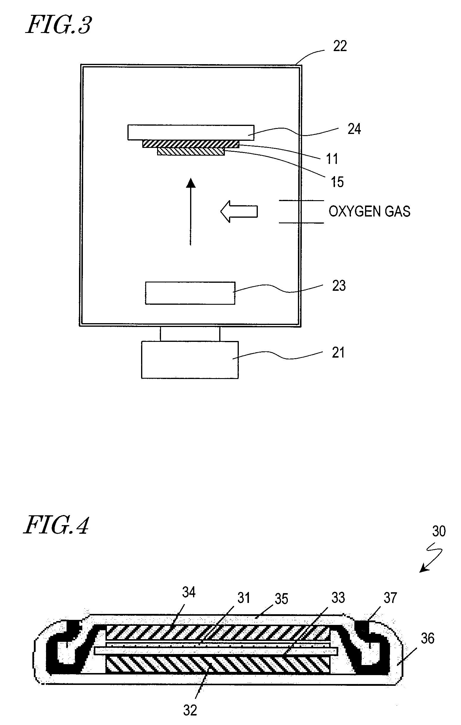
[0116]First, by using a production apparatus having the structure shown in FIG. 3, a negative-electrode active material layer was produced on the surface of a current collector. The production method will be specifically described.

[0117]In advance, silicon tablets (with a purity of 99.99% or more) were inserted in the carbon crucible 23, which was placed within the vacuum chamber 22, and after setting the pressure within the vacuum chamber 22 to 0.005 Pa, an oxygen gas was introduced at a flow rate of 70 sccm, and the pressure within the vacuum chamber 22 was set to 0.13 Pa.

[0118]Thereafter, under the conditions of voltage: −9 kV and EB current: 400 mA, an electron beam was radiated from the electron gun onto the aforementioned silicon tablets, thus allowing the silicon to melt and vapor-deposited onto the current collector 11, which was disposed so as to oppose the carbon crucible 23. As the current collector 11, a copper foi...

example 2

[0132]A negative-electrode active material layer and a coin battery of Example 2 were produced by methods similar to Example 1, except that the oxygen gas flow rate was increased from 70 sccm to 90 sccm when the film thickness (thickness of the negative-electrode active material body) reached 10 μm. Next, by methods similar to Example 1, oxygen concentration measurements of the negative-electrode active material layer and a charge-discharge characteristics evaluation of the coin battery were taken. The results thereof will be described.

[0133]As a result of performing x-ray fluorescence spectrometry for the negative-electrode active material body (SiOx) in the negative-electrode active material layer of Example 2, the x value was found to be 0.59.

[0134]Moreover, results of measuring the Si2p binding energy along the depth direction of the negative-electrode active material layer of Example 2 by x-ray photoelectron spectroscopy are shown in FIG. 8(a).

[0135]As can be seen from FIG. 8(a...

example 3

1. Production of Negative-Electrode Active Material Layer

[0160]In the present Example, a negative-electrode active material layer was produced by using a vapor deposition apparatus (manufactured by ULVAC, Inc.). First, with reference to FIG. 16, the construction of the vapor deposition apparatus used in the present Example will be described.

[0161]The vapor deposition apparatus 50 includes a chamber 56 and an evacuation pump (not shown) for evacuating the chamber 56. Inside the chamber 56 are a stage 54 on which to fix a current collector 51, tubing 53 for introducing an oxygen gas into the chamber 56, a nozzle 52 which is connected to the tubing 53 for emitting the oxygen gas, and an evaporation source 55 for supplying silicon onto the surface of the current collector 51. Although not shown, an electron beam heating means for evaporating the material of the evaporation source 55 is also comprised. The tubing 53 is connected to an oxygen cylinder via a mass flow controller. The nozzl...


PUM

PropertyMeasurementUnit
thicknessaaaaaaaaaa
thicknessaaaaaaaaaa
thicknessaaaaaaaaaa

Abstract

A negative electrode 100 for a lithium secondary battery includes: a current collector 11; a negative-electrode active material body 12 supported by the current collector 11, the negative-electrode active material body 12 having a chemical composition represented as SiOx (0.1≦x≦1.2); and a covering layer 14 formed on the negative-electrode active material body 12, the covering layer 14 having a chemical composition composed of silicon dioxide. The covering layer 12 has a thickness which is greater than 1 nm and no more than 10 nm.

Description

TECHNICAL FIELD[0001]The present invention relates to a negative electrode for a lithium secondary battery and a method of producing the same, and a lithium secondary battery having a negative electrode for a lithium secondary battery.BACKGROUND ART[0002]There is a trend for downsizing and enhancement in the performance of mobile information terminals such as PCs (Personal Computers), mobile phones, and PDAs (Personal Digital Assistants), and audio-visual devices such as videorecorders and memory audio players, in which lithium-ion secondary batteries are used.[0003]This has led to the desire for higher capacities in lithium-ion secondary batteries. For achieving high capacity, choices and designs of negative-electrode active materials are under study. As negative-electrode active materials for achieving high capacity, metal lithium is being studied, and aluminum, silicon, tin and the like, which are capable of forming alloys with lithium, are being studied (e.g., Non-Patent Documen...

Claims


Application Information

Patent Timeline
Patent Type & Authority Applications(United States)
IPC IPC(8): H01M4/02H01M4/48H01M4/04H01M10/40H01M4/13B82Y99/00H01M4/139H01M4/36H01M4/70
CPCH01M4/131H01M4/366Y02E60/122H01M10/0525H01M2004/027H01M4/485Y02E60/10H01M4/02H01M4/04H01M4/48H01M4/64
Inventor IWAMOTO, KAZUYA
Owner PANASONIC CORP
Learn More