High pressure discharge lamp operation device, light source device, and projection type image display device

Active Publication Date: 2009-05-07
PANASONIC CORP
View PDF10 Cites 3 Cited by
  • Summary
  • Abstract
  • Description
  • Claims
  • Application Information

AI Technical Summary

Benefits of technology

[0020]The present invention was conceived in view of the above problem, and aims to offer a lighting method which can suppress a decline in an optical output and a shortening of a lamp life without changing the operating frequency of the lamp.Means of Solving the Problems
[0027]According to the lighting method of the present invention, even when the lighting voltage falls below the first voltage value V1 due to a shortened distance between the lamp electrodes caused by formation of the protuberance over the course of the operating time, as long as a predetermined condition is satisfied, the switching voltage is changed to the second voltage value V2, which is lower than the first voltage value V1. Consequently, the discharge of the high-pressure discharge lamp is maintained by the constant power control, and the life can be maintained by suppressing a decline in the optical output and a shortening of the life due to blackening.

Problems solved by technology

Formation of such a protuberance shortens a distance between the electrodes, lowering the lamp voltage as a result.
As a result, an optical output (illuminance) may decline due to a lack of power applied to the lamp, and a life of the lamp may be shortened by a so-called “blackening phenomenon” caused by a fall in a lamp temperature also due to the lack of power.

Method used


Image

  • High pressure discharge lamp operation device, light source device, and projection type image display device
  • High pressure discharge lamp operation device, light source device, and projection type image display device
  • High pressure discharge lamp operation device, light source device, and projection type image display device

Examples


first embodiment

[0055]The present embodiment describes a lamp provided in a lamp unit, and a lighting method and lighting apparatus for the lamp.

[0056]In the present embodiment, a lamp unit using a high-pressure mercury lamp in accordance with the present invention is described with reference to drawings.

1. Structure of Lamp Unit

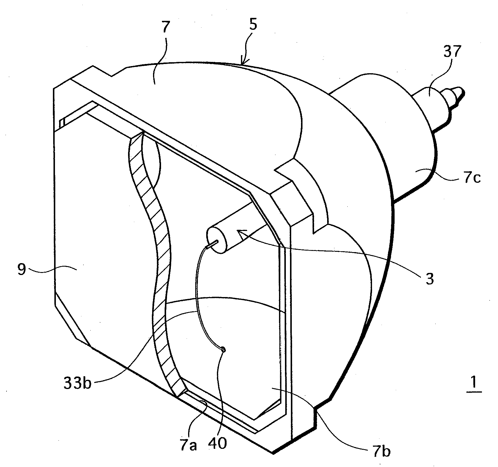
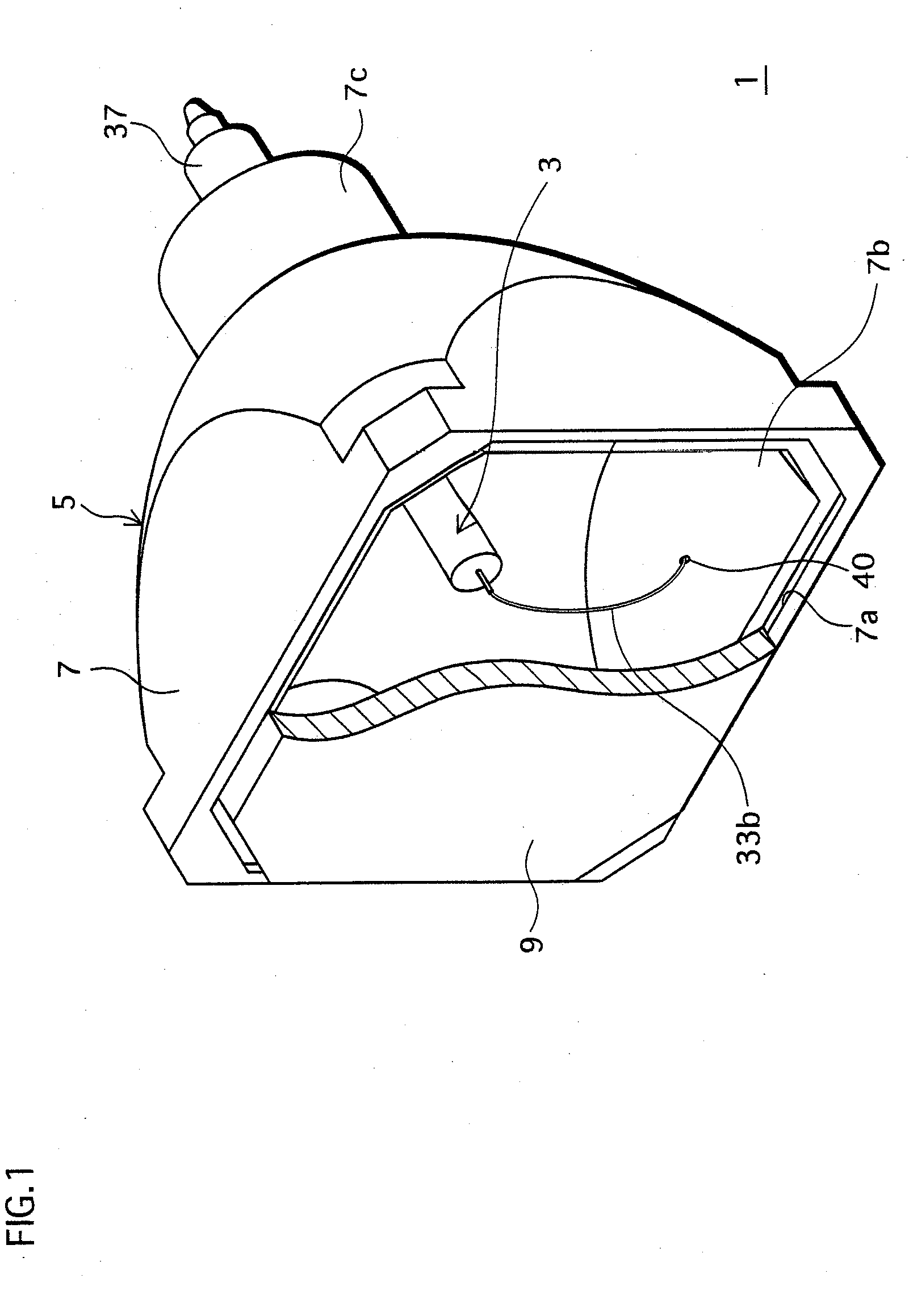
[0057]FIG. 1 is a perspective view of the lamp unit in the present embodiment.

[0058]The lamp unit 1, as shown in FIG. 1, includes a high-pressure mercury lamp (hereinafter, simply referred to as “lamp”) 3 and a reflecting mirror 5, where the lamp 3 is built in the reflecting mirror 5.

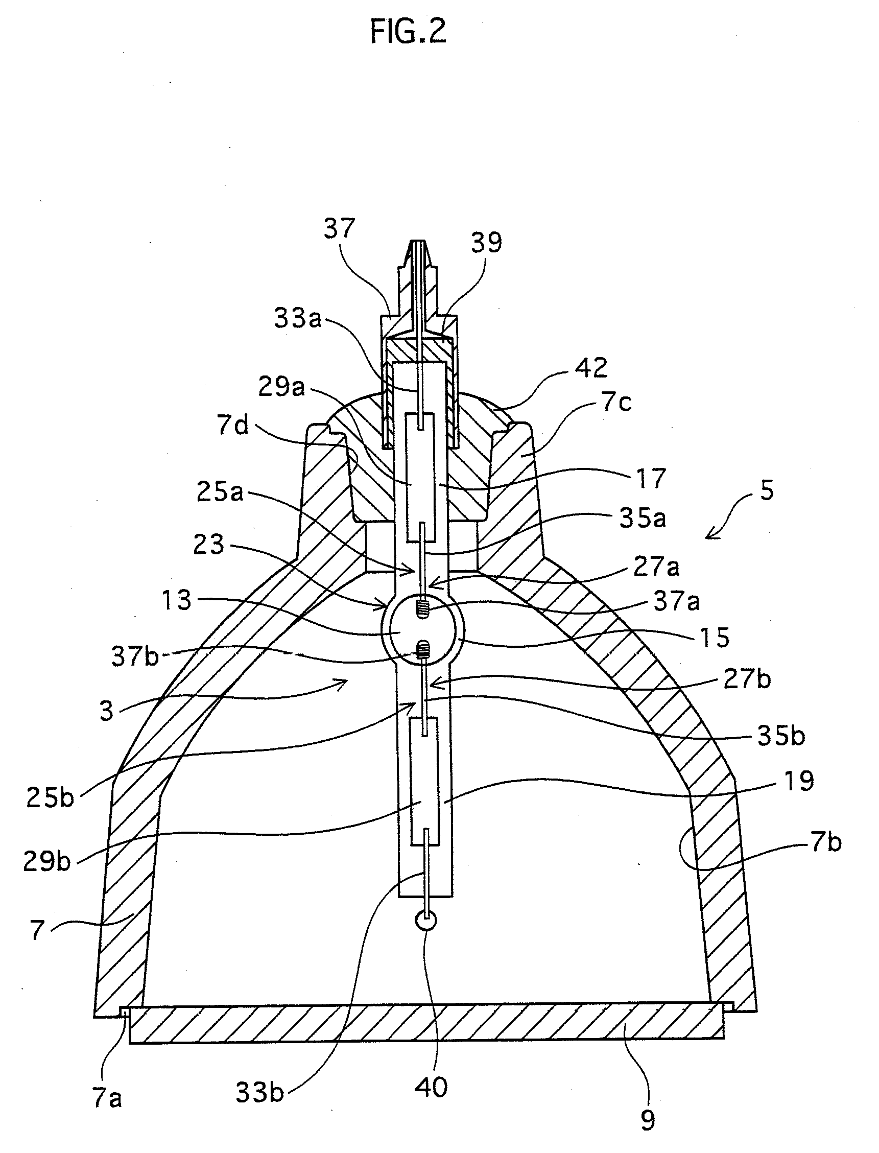
[0059]FIG. 2 is a plan view of the lamp unit, where the reflecting mirror is cut away so as to provide a clear view of an inner structure of the lamp.

1-1. Structure of Lamp

[0060]As shown in FIG. 2, the lamp 3 includes a discharge vessel 23 which has a discharge space 13 therein and electrode assemblies 25a and 25b. The electrode assemblies 25a and 25b are hermetically sealed with two sealing pa...

embodiment

4. Embodiment

4-1. Lamp

[0098]Here, the lamp 3 is considered to be used as, for instance, a projection-type image display apparatus and the like, and thus will be described accordingly. The lamp 3 is a so-called “short arc” type lamp, where a gap (a distance between the electrodes) is set in a range of 0.5 mm to 2.0 mm in order to make the lamp closer to a point source of light.

4-2. DC / DC Converter

[0099]FIG. 6 is a circuit diagram of the DC / DC converter.

[0100]The DC / DC converter 54 includes, for example, an inductor L0, a switching element Q0, a diode D0, and a smoothing capacitor C0. In other words, the DC / DC converter 54 is a publicly known step-down converter. Note that as the switching element Q0, for example, an N-type field-effect transistor is used.

[0101]The switching element Q0 adjusts a current outputted to the DC / AC inverter 55 by switching ON / OFF based on the power setting signal. That is to say, the power setting signal is a pulse signal for the switching element Q1 to swi...

second embodiment

[0118]In the first embodiment, a description was made on the lamp unit and the lighting apparatus which lights the lamp attached to the lamp unit.

[0119]In the second embodiment, a description will be made on a DLP (registered trademark) front-projection type image display apparatus which includes the lamp unit and the lighting apparatus described in the first embodiment.

[0120]FIG. 10 is an overall diagram of the front-projection type image display apparatus, where part is cut away to provide an inner view of the lamp, in the second embodiment.

[0121]A front-projection type image display apparatus (hereinafter, referred to as “projector”) 100 is a DLP (registered trademark) type apparatus with a single DMD (registered trademark) chip.

[0122]As shown in FIG. 10, the projector 100 is constituted from a power unit 102 including the above-mentioned lighting apparatus, the above-mentioned lamp unit 1, an image unit 104 which performs an optical system and image processing, a control unit 10...


PUM


Abstract

Provided is a method for lighting a high pressure discharge lamp capable of increasing the life thereof. The lighting method is as follows. When the time elapse after lighting up the discharge lamp is within a predetermined condition (e.g. 5 minutes or less), constant current control is performed if the lamp voltage is lower than switching voltage (here, a first voltage value V1) and constant power control is performed to maintain the lamp power at a power value W1 if the lamp voltage is equal to or above the switching voltage. After the predetermined condition (5 minutes) is exceeded, the constant power control is performed by lowering the value of the switching voltage from the first voltage value V1 to the second voltage value V2. If the lamp voltage is equal to or above the switching voltage lowered, the lamp power is maintained at power value W1.

Description

TECHNICAL FIELD[0001]The present invention relates to a lighting method, lighting apparatus, and light-source apparatus for a high-pressure discharge lamp and a projection-type image display apparatus.BACKGROUND ART[0002]In recent years, high-pressure mercury lamps have been widely used as a light source for liquid crystal panels, DLP (Digital Light Processing: Registered Trademark) projection-type display apparatuses and the like.[0003]For example, the above-mentioned high-pressure mercury lamp (hereinafter, simply referred to as “lamp”) is composed of a bulb made of a quartz glass, including therein a pair of tungsten electrodes and enclosing a rare gas such as mercury or argon and a halogen such as bromine. The pair of tungsten electrodes are disposed opposing each other with a predetermined gap in between.[0004]Also, the above lighting apparatus normally performs a control on a lamp voltage and a lamp power such that a control characteristic is as shown in FIG. 13. That is to sa...

Claims


Application Information

Patent Timeline
IPC IPC(8): G03B21/00H05B41/36
CPCG03B21/14H04N9/3114H04N9/3155Y02B20/208H05B41/2882H05B41/2928H05B41/38H04N9/3197G03B21/2026Y02B20/00
Inventor IKEDA, MASARUONO, SYUNSUKEOZASA, MINORUYAMAMOTO, MASAHIROYAMADA, GO
Owner PANASONIC CORP
Why Eureka
Try Eureka