
High Efficiency Intake Hood System For Mobile Sweeper Vehicles

Inactive Publication Date: 2009-05-07
SCHWARZE INDS
View PDF5 Cites 12 Cited by
  • Summary
  • Abstract
  • Description
  • Claims
  • Application Information

AI Technical Summary

Benefits of technology

[0007]An improved pickup or intake hood for a roadway / pavement cleaning vehicle, such as a wheeled regenerative roadway / pavement sweeper, includes an intake hood having a central compartment into which air is introduced from the outlet of a recirculation fan at a high-velocity to entrain dust, particulates, and the like therein and from which the particulate-entrained air flow is provided via appropriate ducting to a dust separation system to remove the entrained material with the remaining air flow provided to the inlet of a recirculation fan. Dust conduits lead from appropriately shrouded gutter brooms into a flow control manifold or selector box that allows dust from one or both of the gutter brooms to be drawn into a duct for transport to the dust separation system. The intake hood is provided with at least one auxiliary compartment adjoining or adjacent the primary air flow compartment and into which any fugitive air flows from the primary air flow compartment can enter. The auxiliary compartment is in air flow communication with the dust separation system via ducting connected to the dust separation system so that any fugitive particulates are directed into the dust separation system to minimize the escape of fugitive dust and particulates.

Problems solved by technology

It is known that some of the air flow in the intake hood can escape from beneath one or more of the various sides of the hood into the ambient environment; that escaping air flow can carry entrained particulates, known as ‘fugitive’ particles, into the ambient environment and undesirably contribute to the concentration of airborne particulates surrounding the cleaning vehicle.

Method used


Image

  • High Efficiency Intake Hood System For Mobile Sweeper Vehicles
  • High Efficiency Intake Hood System For Mobile Sweeper Vehicles
  • High Efficiency Intake Hood System For Mobile Sweeper Vehicles

Examples


Embodiment Construction

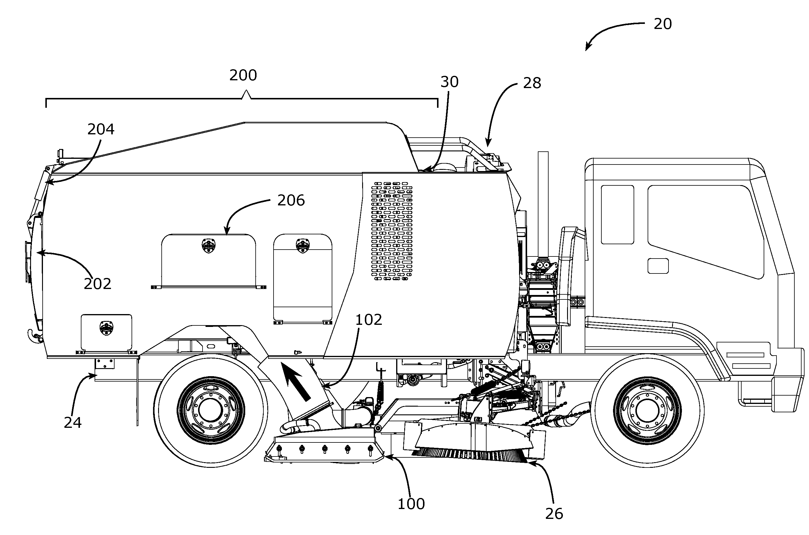
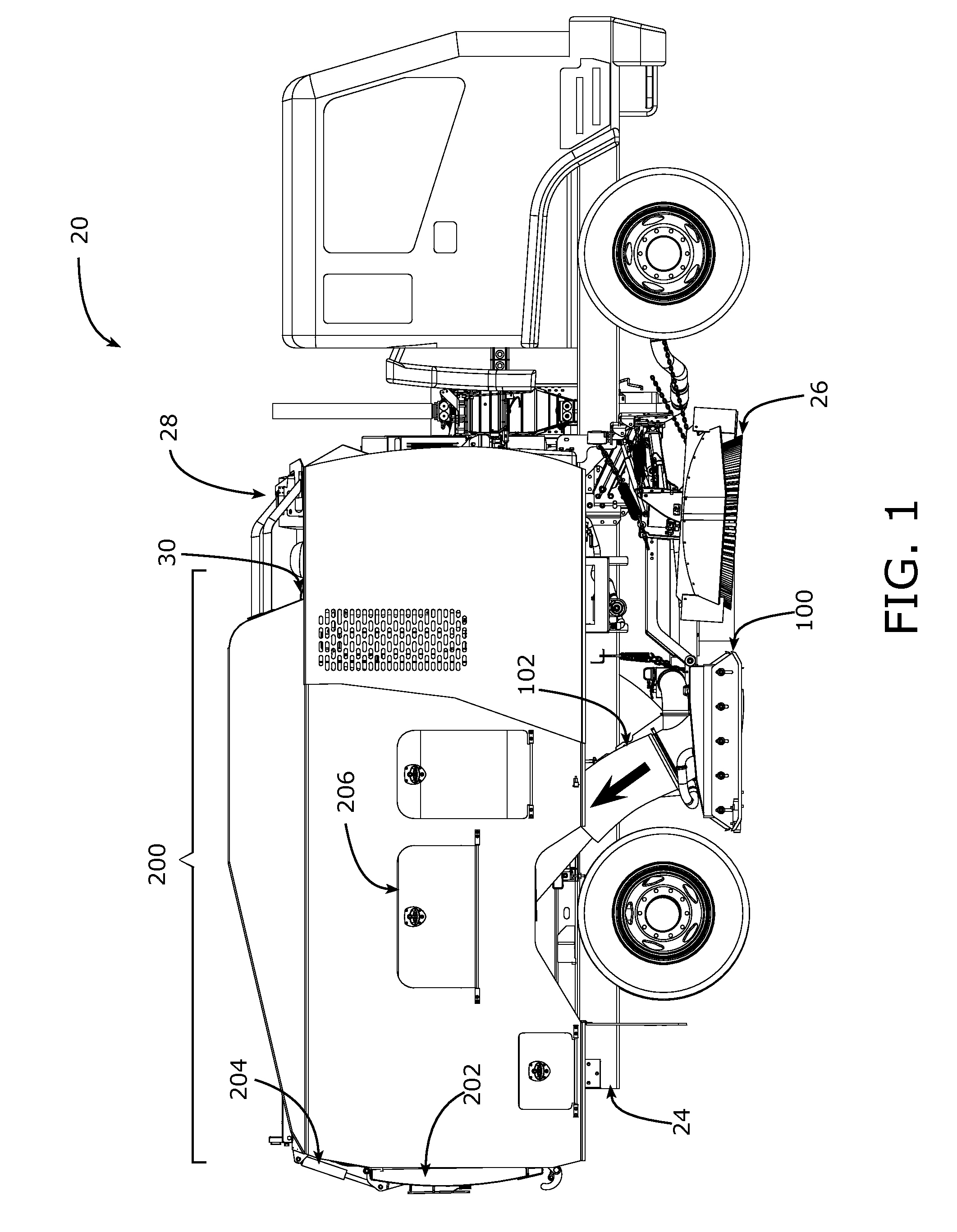
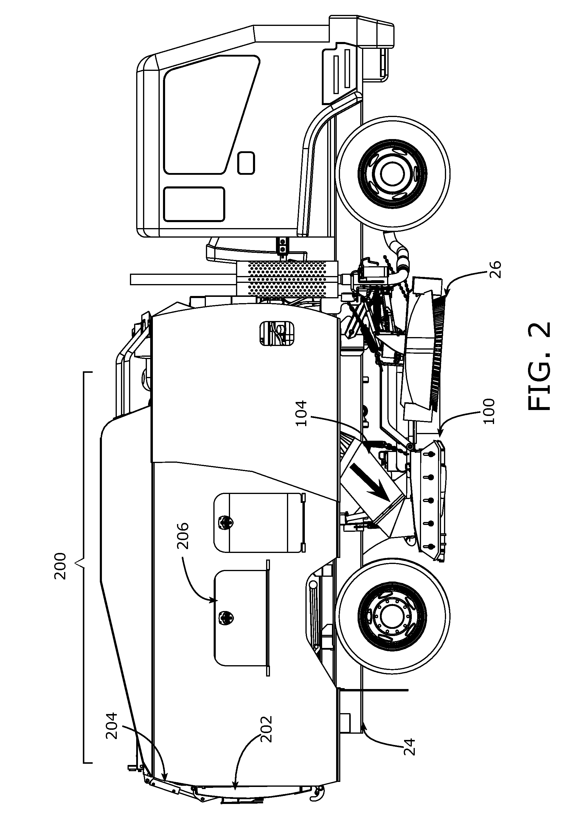
[0020]An exemplary pavement / street cleaning vehicle with a dust / particulate separation system in accordance with the preferred embodiment is shown in right and left side views in FIGS. 1 and 2 and is generally designated by the reference character 20; the particular sweeper configuration shown is representative of sweepers manufactured by Schwarze Industries, Inc. of Huntsville, Ala. 35811 under the DXR designation.

[0021]As shown in FIGS. 1 and 2, the truck-mounted sweeper system 20, which can be mounted on a commercial truck chassis, includes a pickup head or debris-intake hood 100 carried beneath the truck frame 24, an optional gutter broom 26 that is mounted forwardly of the debris-intake hood 100 on one or both sides thereof (as shown in the top view of FIG. 3), and a power unit 28 that includes (not specifically shown) a high-volume, high-velocity radial flow fan 30, an internal combustion engine for driving the fan 30, and associated hydraulic pump(s), air compressor(s), and v...


PUM


Abstract

An improved pickup or intake hood for use in regenerative air flow road and pavement sweeper vehicles includes at least one side auxiliary plenums and / or at least one side-to-side plenum adjacent the primary air flow compartment. The auxiliary plenums are attached by appropriate ducting into the regenerative air flow so that any fugitive air and or dust flows from the primary air flow compartment are captured in the auxiliary plenums to minimize fugitive air and / or dust flows into the ambient atmosphere. Dust conduits from shrouded gutter brooms enter a manifold box to allow dust-entrained air flows from one or both gutter brooms to enter into the regenerative air flow to capture dust generated by the gutter brooms.

Description

CROSS-REFERENCE TO RELATED APPLICATION[0001]This application claims the benefit of U.S. Provisional Patent Application 60 / 985,625 filed Nov. 5, 2007 in common assignment herewith.BACKGROUND OF THE INVENTION[0002]Various types of vehicles have been developed to sweep or vacuum debris from pavements, roadways, and streets. In general, these vehicles can be classified as mechanical broom sweepers, air sweepers, and combinational variants thereof.[0003]Mechanical broom sweepers use a motor-driven broom or brooms to mechanically sweep paper, plastic, litter, trash, vegetation (leaves, twigs, grass clippings, etc.), asphalt and concrete debris, and larger sand or gravel particles toward a conveyor for transport into a debris collection hopper.[0004]Regenerative air sweepers use a motor-driven fan to create a high-velocity recirculating air flow to aspirate dust, particulates, and other debris from the pavement or street surface through an intake or pickup hood carried or suspended beneath...

Claims


Application Information

Patent Timeline
IPC IPC(8): E01H1/05E01H1/08
CPCE01H1/0872E01H1/053
Inventor STELL, EDWARD B.
Owner SCHWARZE INDS
Learn More